or Call 01642 931 329 to discuss alternatives
Megger MFT1741+ Multifunction Tester & EVCA210-UK EV Charge-Point Adapter Kit
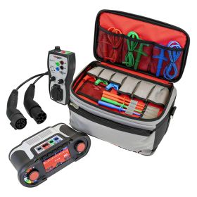
This kit provides you with 2 top of the range testing devices from Megger for EVSE testing. The Megger EV Test Kit includes a Megger MFT1741+ Multifunction Electrical Installation Tester and a Megger EVCA210-UK Electrical Vehicle Charger Adaptor. Test 6mA DC RCDs and EV charging stations, complying with the IET 18th edition. The EV Adaptor can test Mode 3 AC electric vehicle charge points, single or three-phase.
Megger MFT1741+ Multifunction Tester Overview
The Megger MFT1741+ Multifunction Tester can be used to troubleshoot and verify the functionality and safety of industrial, commercial and domestic fixed wiring installations, as well as electric vehicle charging points (when used with the Megger EVCA210-UK Electric Vehicle Charge-Point Adapter). It is particularly well suited to testing low voltage electrical installations in areas with high electrical noise.
The Megger MFT1741+ includes all the tests required to complete the electrical certification for the aforementioned systems
Testing Capabilities
Insulation Ranges | |
100 V | X |
250 V, 500 V | X |
1000 V | X |
Test voltage display | X |
Adjustable buzzer threshold | X |
Note | Includes input protection against live circuits up to 600V even when the insulation test is locked on. |
Continuity and Resistance Ranges | |
200 mA test | X |
15 mA test | X |
Adjustable buzzer threshold | X |
Loop Testing | |
2 and 3 wire non-tripping L-PE 50 V ~ 280 V | X |
2 wire Hi current L-N 50 V ~ 280 V | X |
2 wire phase to phase L-L 50 V ~ 500 V | X |
PSCC and PFC (20 kA max.) | X |
Max. Zs display | X |
R1 + R2 value | - |
Touch voltage display on faulty earth | X |
Earth Electrode Test | |
2 and 3 pole * | X |
3 pole ART and Stakeless method * | X |
RCD Test | |
1/2, 1, 5 x I and ramp RCD test | X |
Auto RCD test | X |
Type AC, A and S RCDs | X |
Type B (pure DC) RCDs | X |
Programmable RCD | X |
3-phase RCD (no earth) | X |
10, 30, 100, 300 and 500 mA RCD | X |
Auto sequence for EV charge point RCDs* | X |
Other Features | |
Supply measurement | X |
True RMS (Voltage and Frequency) | X |
Leakage current measurement * | X |
Phase rotation | X |
Calibration certificate | X |
Rechargeable batteries (charger included) | X |
SP5 Switched probe included | X |
Warranty from Megger upgradeable to 3 years FREE | X |
Onboard memory with Bluetooth® download | X |
CAT IV 300 V / CATIII 600 V | X |
Hard moulded case | - |
Soft pouch with additional storage | X |
Confidence meter noise reduction | X |
New hardware loop test platform | X |
Notes | * requires optional accessory |
X = Included | |
- = Not Included |
Further to the above, the tester includes visual and audible hazardous voltage indicators. If a live voltage is detected during insulation or continuity tests the MFT1741+ will alert the user by indicating the voltage on the display. If this voltage exceeds a safe value, it will issue a warning beep and prevent the user from carrying out any further tests on the system. This protects both the user and tester from damage.
Testing Features
Non-Trip Loop Impedance Technology
In addition to increasing the efficiency of testing, non-trip loop impedance technology also prevents RCDs from influencing the total loop impedance value. As a result of this technology non-trip loop impedance tests can be performed in eight seconds.
Confidence Meter
The confidence meter illustrates the degree of confidence in the accuracy of the loop impedance measurement. The digital ARC indicates the analytical process and the measurement is continually monitored and adjusted with regard to the circuit noise. As loop impedance values are particularly susceptible to changes in circuit noise, the confidence meter has been included to indicate the reliability of these measurements.
Auto Sequence for EV Charge Point RCDs
When used with the Megger EVCA210-UK Electric Vehicle Charge-Point Adapter (see below), the Megger MFT1741+ Multifunction Tester can be used to test electric vehicle charge points. To this end, the multifunction tester includes an automatic EV charge point RCD test sequence including a 6mA DC test.
Simple-to-Use & Ergonomic
Measurements are displayed on the large, clear, backlit, dual-readout display. Readings and test parameters are displayed in parallel; it also includes a digital/ analogue arc for indicating fluctuating readings.
The colour-coded function controls make accessing the test function and measurement range simple. These controls reduce the possibility of selecting an incorrect function or range. Furthermore, the tester does not include hidden or complicated measurement menus which also adds to the tester’s ease of use.
Also improving the ease-of-use is its ambidextrous design; it has TEST and LOCK functions on either side of the unit ensuring that it can be operated by both right- and left-handed users. Moreover, it supports hands-free operation as it features an automatic test start. This is particularly useful in situations where it is not practical for the user to press the TEST button, for instance, when he/she is holding probes and/or using the MFT while on a ladder. The supplied neck strap also facilitates hands-free operation as it can be hung around the user’s neck.
The MFT has been designed to stand independently. It also features an ingress protection rating of IP54, ensuring that it is resistant to dust and water ingress, and is powered by internal rechargeable batteries. The tester has a battery life of approximately four hours.
Overall it is an easy-to-use and ergonomic test instrument with an eclectic array of test functions. It can be used, amongst other things, to verify the functionality and safety of EV charge points.
Megger MFT1741+ Multifunction Tester Key Features
- Troubleshoot and verify the functionality and safety of industrial, commercial and domestic fixed wiring installations
- Check EV charge points using the Megger EVCA210-UK (see below)
- Ideal for testing low voltage electrical installations in areas with high electrical noise
- Includes all the tests required to complete the relevant electrical certification
- Please see the table above for an overview of the MFT1741+’s testing capabilities
- Visual and audible hazardous voltage indicators
- Stops testing if a hazardous voltage is detected during insulation and continuity tests
- NEW non-trip loop impedance technology
- NEW confidence meter
- NEW auto sequence for EV charge point RCDs
- Large, clear, backlit, dual-readout display
- Readings and test parameters are displayed in parallel
- Digital/ analogue arc for indicating fluctuating readings
- Colour-coded function controls
- Function controls reduce the possibility of selecting the incorrect function or range
- Does NOT include hidden or complicated measurement menus
- Ambidextrous design: TEST and LOCK functions on either side
- Automatic test start supports hands-free operation
- Supplied with a neck strap
- Stands independently
- IP54
- Powered by internal rechargeable batteries
- Approximate battery life: four hours
- Easy-to-use and ergonomic test instrument with an eclectic array of test functions
Megger EVCA210-UK Electric Vehicle Charge-Point Adapter Overview
The Megger EVCA210-UK Electric Vehicle Charge-Point Adapter can be used with the Megger MFT1741+ Multifunction Tester to verify the functionality and safety of single- and three-phase electric vehicle charge points according to IEC/ EN 61851-1 and IEC/HD 60364-7-722.
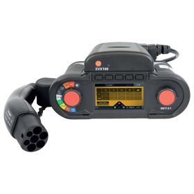
The MFT1741+ can be front-mounted onto the Megger EVCA210-UK Electric Vehicle Charge-Point Adapter via its mains socket. The Charge-Point Adapter also includes 4mm connection ports (L1, L2, L3, N and PE) and a CP signal terminal to which an oscilloscope can be connected, allowing the user to measure CP signals.
Furthermore, the Megger EVCA210-UK is supplied with a type 2 connector for testing charging points with a panel-mounted socket or a fixed cable with a vehicle connector, and a type 1 connector for checking charging points with a fixed type 1 cable connector, such as those found on a Mitsubishi PHEV. It provides all the functions required to fully test Mode 3 AC electric vehicle charge points.
The Electric Vehicle Charge-Point Adapter simulates the connection of an electric vehicle to the charge point. Using the rotary switch, the user can set the adapter to imitate Proximity Pilot (PP) or Control Pilot (CP) charging states.
It can be used to simulate a CP “E” Error, an error on the control pilot circuit, or a PE Error (Earth Fault), which simulates the disconnection of the PE circuit. These manual tests can be easily engaged by pressing their corresponding function button; both error simulations can be used to check that the output of the charge point is disconnected correctly.
It also includes a manual PE Pre-Test which can be used to check whether dangerous voltages are present on the PE circuit. This test should be performed prior to commencing other checks; if the charging point fails this test any further investigation should be stopped until the fault has been found and resolved.
In addition to maintaining compliance with UK, European and other international wiring standards, the Megger EVCA210-UK Electric Vehicle Charge-Point Adapter has a safety rating of CAT II 300V and an ingress protection rating of IP54. It also conforms with the Low Voltage Directive LVD 2014/35.
Overall it is a compact and simple-to-use adapter specifically designed for testing the safety and functionality of electric vehicle charging stations.
Megger EVCA210-UK Electric Vehicle Charge-Point Adapter Key Features
- Use with the Megger MFT1741+ (see above) to verify the safety and functionality of EV charge points
- Suitable for checking single- and three-phase EV charge points
- Check EV charge points in accordance with IEC/EN 61851-1 and IEC/ HD 60364-7-722
- Mains socket
- 4mm connection points: L1, L2, L3, N and PE
- CP signal terminal for connecting an oscilloscope to measure the CP signals
- Type 2 connector for testing charging points with panel-mounted sockets or a fixed cable with a vehicle connector
- Type 1 connector for checking charging points with a fixed type 1 cable connector, such as those found on a Mitsubishi PHEV
- Simulates the connection of an EV to a charge point
- PP charging state simulation
- CP charging state simulation
- Rotary switch
- Push-button for CP Error “E” simulation
- Push-button for PE Error (Earth Fault) simulation
- Push-button for PE Pre-Test
- Compliant with UK, European and international wiring standards
- IP54
- CAT II 300V
- Conforms with the Low Voltage Directive LVD 2014/35
- A compact and simple-to-use adapter for testing EV charge points
Videos
What’s Included?
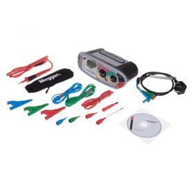
Megger MFT1741+ Multifunction Tester
- Printed Quick Start Guide
- Full User Guide (CD)
- Calibration Certificate
- Megger SP5 Switched Probe
- Megger Neck Strap
- 3-Wire Lead Set with Prods and Clips
- Mains Plug Test Lead (BS 1363)
- AC Battery Charger
- Large Soft Pouch with Extra Storage
Megger EVCA210-UK Electric Vehicle Charge-Point Adapter
- Type 1 Charging Plug
- Type 2 Charging Plug
- Soft Carry Case
- Instruction Manual
- 50M R2 Extension Wander Test Lead (PVC Cable Reel) - TSTL50M, typically £49.00
- Lockout Starter Kit - Incl. Hasps, Padlocks, Tags, MCB Lockout & More - LT-LPP, typically £25.00
- TestSafe Fibreglass Fish Tape Cable Puller – 30m - TS-FG-FT-30M, typically £24.99
- Evik 10 Piece Cable Pulling Fibreglass Rods, Standard Kit in Tube - EV-STD-KIT-T, typically £39.00
Megger MFT1741+ Multifunction Tester Technical Specifications
Insulation Test | ||
Output voltage | -0% +20% at rated load or less | |
Voltage display | ±3% ±3 digits ±0.5% of rated voltage | |
Short circuit current | 1.5 mA nominal test current | |
Test current on load | 1 mA at min pass values of insulation | |
Insulation Accuracy | ||
1000 Volts | 10 kΩ ~ 999 MΩ | ±3% ±2 digits |
500 Volts | 10 kΩ ~ 500 MΩ | ±3% ±2 digits |
>500 MΩ | ±10% ±4 digits | |
250 Volts | 10 kΩ ~ 250 MΩ | ±3% ±2 digits |
>250 MΩ | ±10% ±4 digits | |
100 Volts | 10 kΩ ~ 100 MΩ | ±3% ±2 digits |
>100 MΩ | ±10% ±4 digits | |
Resistance and Continuity | ||
0.01 Ω ~ 99.9 Ω | ±2% ±2 digits | |
100 Ω ~ 99.9 kΩ | ±5% ±2 digits | |
Open circuit voltage | 5 V ±1 V | |
Test current (user selectable) | (0 Ω ~ 2 Ω) | |
205 mA ±5 mA | ||
15 mA ±5 mA (user selectable) | ||
Loop Test | ||
Live to earth/neutral supply | 48 V ~ 280 V (45 Hz ~ 65 Hz) | |
Live to live supply | 48 V ~ 500 V (45 Hz ~ 65 Hz) | |
L-N/L-L tests | ±5% ±5 digits | |
L-E tests | 0.1 Ω ~ 39.9 Ω | ±5% ±5 digits ± noise margin |
40.0 Ω ~ 1000 Ω | ±10% ±5 digits | |
Display range | 0.01 Ω ~ 1000 Ω | |
Live to earth PFC range | 20 kA | |
Live to live PSCC range | 20 kA | |
Notes |
† Reference conditions apply For test environments see service data |
|
RCD Tests | ||
Supply up to 100 mA | 48 V ~ 480 V (45 Hz ~ 65 Hz) | |
Supply up to 1 A | 48 V ~ 280 V | |
RCD type | Type AC, A, S | |
Type B (pure dc) | ||
No trip test | (1/2xI) | –10% ~ –0% |
Trip test | (1xI, 2xI and 5xI)+0% ~ +10% | |
EV | 30 mA ac, 6 mA dc (Mode 1 + 2) | |
(Mode 1 + 2) Ramp Test | ||
Touch voltage (0 ~ 253 V) | +5% +15% ±0.5 V | |
Trip time | ±1% ±1 ms | |
Trip current | ±5% | |
Step Increments | ||
VAR (variable RCD selection) | 10 mA ~ 50 mA | 1 mA steps |
50 mA ~ 500 mA | 5 mA steps | |
500 mA ~ 1000 mA | 10 mA steps | |
Supply Measurement | ||
Voltage | 10 V ~ 600 V | |
(15 ~ 400 Hz) True RMS | ||
±3% ± 1 V ±2 digits | ||
Phase rotation indication | L1–L2–L3 and L1–L3–L2 | |
Frequency | 15 Hz ~ 99 Hz ±0.5% ±1 digit | |
100 Hz ~ 400 Hz ±2.0% ±2 digits | ||
Frequency resolution | 0.1 Hz | |
Power Supply | ||
Batteries | IEC LR6 type AA alkaline (6 cells - supplied) or 1.2 V NiMH (rechargeable pack of 6 – supplied) | |
Mains charger for on-board re-charging (4 hours typical) 12 V car charger (cigar lighter lead - optional) | ||
Earth/ Ground Test | ||
Resolution | 0.01 Ω | |
Current | 0.45 mA or 4.5 mA | |
Noise rejection | 20 V pk/pk (7 V rms) | |
Max probe resistances | Rp and Rc | |
100 kΩ @ 50 V | ||
5 kΩ @ 25 V | ||
2 and 3 pole method | (0.01 Ω ~ 1.999 kΩ) | |
±2.0% ±5 digits | ||
ART method (1.00 Ω ~ 1.999 kΩ) | ||
±5.0% ±5 digits* | ||
Stakeless method | (1.00 Ω ~ 199 Ω) | |
±7.0% ±5 digits* | ||
Current | ||
(via optional clamp meter) | ±5.0% ±3 digits. | |
Range | 0.1 mA to 200 A ac | |
Resolution | 0.1 mA | |
mV Sensor Input | ||
Including temperature (third party module) | ±1.0% ±2 digits | |
Range | 0.0 mV to ±199.9 mV dc | |
Resolution | 0.1 mV | |
Data storage | ||
Capacity | 1000 results | |
Bluetooth® communication | ||
Safety | IEC 61010-1:2010 | |
IEC 61010-30:2010 | ||
IEC 61010-031:2008 | ||
600 V CAT III / 300 V CAT IV | ||
(Max Phase to Phase 600 V) | ||
IEC 61557:2007 parts 1 to 10 | ||
EMC | IEC61326 edition 2 location class B | |
Operating temperature range and humidity | -10 °C ~ +55 °C | |
90% R.H. at +40 °C max | ||
Storage temperature range and humidity | -25 °C ~ +70 °C | |
Maximum altitude | 2000 m | |
Weight (instrument and case) | 1 kg (with batteries, excluding case) | |
Dimensions (instrument and case) | 220 mm H x 390 mm W x 285 mm D | |
IP rating | IP54 | |
Calibration temperature | +20 °C | |
Temperature coefficient | <0,1% per °C For test environments see service data. |
Megger EVCA210-UK Electric Vehicle Charge-Point Adapter Technical Specifications
Input voltage | Up to 250 V (single phase system) / up to 430 V (three phase system) |
Input Frequency | 50/60 Hz |
PE Pre-Test | Yes - Push button |
CP Error “E” simulation | Push button |
PP Simulation | NC, 13 A, 20 A, 32 A, 63 A |
CP States | A, B, C, D |
CP Error “E” | Yes |
PE Error (Earth fault) | Yes |
Measuring Ports L1, L2, L3, N and PE | Max. 250/430 V, CAT II 300 V, max. 10 A |
Mains socket | Max. 250 V, CAT II 300 V max. 10 A, |
Note: Do not load mains socket simultaneously with measuring ports! |
|
CP Signal Test Ports | Approx. +/-12 V, CAT 0 (under normal condition) |
In case of wrong wiring or error of the charging station these terminals |
|
Measurement category | CAT II 300 V |
Altitude above sea level. | 2000 m max |
Weight | Approx: 780g |
IP-rating | IP54 |
CE directive | Low Voltage Directive LVD 2014/35/EU |
Safety | IEC/EN 61010-1:2010 |
IEC/EN 61010-2-030:2010 | |
Working temperature range | 0 ... +40 °C |
Storage temperature range | -10 ... +50 °C |
Reference humidity range | 10 ... 60% relative humidity w/o condensation |
Working humidity range | 10 ... 85% relative humidity w/o condensation |
Reviews
SKU | EVTESTKIT1 |
---|---|
Manufacturer Part Code | EVTESTKIT1 |
Country of Origin | United Kingdom |