

Important Notice
This item is made-to-order exclusively for you once your order is placed. As a result, it is not eligible for cancellation or return under our standard policy. Your statutory rights remain unaffected.
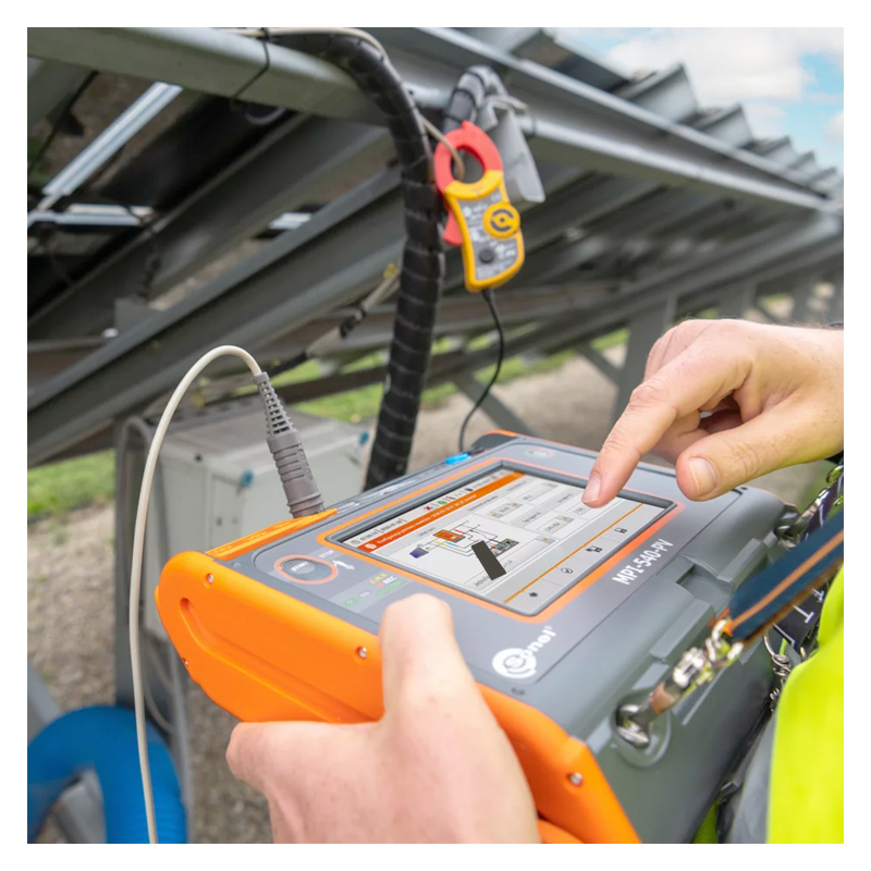
Sonel MPI-540/MPI-540-PV Multifunction Tester

- Large, 7”, colour touchscreen display
- Three-phase power recorder provides power quality diagnostics
- Two versions available: one with photovoltaic testing capabilities and one without
SKU
MPI-540/MPI-540-PV
Sonel MPI-540 / MPI-540-PV Multifunction Tester
The Sonel MPI-540 and MPI-540-PV Multifunction Testers are a comprehensive, ergonomically designed electrical installation tester available with or without photovoltaic testing capabilities; please see the table below for further information.
| SKU | Description | Additional Capabilities |
| MPI-540 | Sonel MPI-540 MFT | n/a |
| MPI-540-PV | Sonel MPI-540-PV MFT with PV Testing | Measure photovoltaic installtions in accordance with the EN 62446 standard:
|
Sonel MPI-540 / MPI-540-PV Multifunction Tester
Delivering exceptional functionality, the Sonel MPI-540/MPI-540-PV Multifunction Testers combine the measuring capabilities of several meters into one without compromising on accuracy. This precise meters measure the following electrical parameters in accordance with class S of the EN 61000-4-30 standard:
- L1, L2, L3 voltage up to 500V
- L1, L2, L3 currents up to 3kA
- Frequency between 40Hz and 70Hz
- Active (P), reactive (Q), and apparent (S) power
- Power factor (PF), cosφ
- Harmonics (up to the 40th for voltage and current)
- Total harmonic distortion (THD) for current and voltage
Moreover, a three-phase power recorded provides advanced power quality diagnostics while an energy cost calculator allows you to work out potential savings quickly. The Sonel MPI-540/MPI-540-PV Multifunction Testers measures all the parameters related to earthing and protection against electric shock and can test fault loop impedance quickly and without triggering RCDs. They also includes automatic installation safety checks for residential, commercial, and industrial electrical installations and supports the following auto measurements:
- Auto mode for RCD tests
- Configurable automatic measurement sequences
- Automatic insulation resistance measurements for 3-, 4-, and 5-conductor cables without switching (with AutoISO-1000C adapter)
Built-in help screens with measurement diagrams guide you through tests, ensuring you can complete checks safely, correctly, and quickly. The eclectic measurement capabilities of these testers combined with its easy operation makes it ideal for commissioning electrical installations in accordance with relevant regulations. It can be used to check:
- Short circuit loop impedance in circuits with or without RCDs
- RCD parameters
- Earth resistance (the tester offers four measurement methods and soil resistivity measurement)
- Continuity of protective and equipotential bondings
- Light intensity
- Phase sequence
- Motor rotation direction
Sonel MPI-540-PV MFT with PV Testing Only
Measure photovoltaic installtions in accordance with the EN 62446 standard:
- Continuity of protective and equipotential bondings
- Earth resistance
- Insulation resistance on DC side
- Open circuit voltage UOC
- Short circuit current ISC
- Work currents and powers on both DC and AC side
- Inverter efficiency
- PV readings are automatically converted to the STC reference conditions
Parameters are displayed in real-time on the 7-inch, large, colour touchscreen display (800x480px). It is supplied with a stylus enabling use with dielectric gloves. Measurements can be saved to the removable SD card and can be downloaded to a PC; data can also be transferred via a USB cable or wirelessly over Bluetooth/Wi-Fi. Sonel offers a variety of software that can be used to analyse and print data, as well as create reports.
The Sonel Multifunction Tester is powered by a Li-ion battery that delivers a long operating time. To ensure it can be used in rugged environments, the Sonel Multifunction Testers is housed in a water- and dust-resistant, IP51-rated casing. It is protected against mechanical damage and its cover can be used to shield the touchscreen display. Finally, the Sonel MPI-540/MPI-540-PV Multifunction Testers have been designed to ensure it is easy to carry.
Overall, these MFT's are rugged, simple-to-use, and accurate tester with an eclectic array of measurement capabilities.
Key Features
- A comprehensive, ergonomically designed electrical installation tester with or without photovoltaic testing
- Combines the measurement capabilities of several meters into one
- Highly accurate
- Measures electrical parameters in accordance with class S of the EN 61000-4-30 standard
- L1, L2, L3 voltage up to 500V
- L1, L2, L3 currents up to 3kA
- Frequency between 40Hz and 70Hz
- Active (P), reactive (Q), and apparent (S) power
- Power factor (PF), cosφ
- Harmonics (up to the 40th for voltage and current)
- Total harmonic distortion (THD) for current and voltage
- Three-phase power recorder provides advanced power quality diagnostics
- Energy cost calculator
- Measures all parameters in relation to earthing and protection against electric shocks
- Test fault loop impedance quickly and without triggering RCDs
- Automatic installation safety checks for residential, commercial, and industrial electrical installations
- Auto mode for RCD tests
- Configurable automatic measurement sequences
- Automatic insulation resistance measurements for 3-, 4-, and 5-conductor cables without switching (with AutoISO-1000C adapter)
- Built-in help screens
- Short circuit loop impedance in circuits with or without RCDs
- RCD parameters
- Earth resistance (the tester offers four measurement methods and soil resistivity measurement)
- Continuity of protective and equipotential bondings
- Light intensity
- Phase sequence
- Motor rotation direction
- Parameters are displayed in real-time
- 7”, large, colour, touchscreen display (800x480px)
- Supplied with a stylus enabling use with dielectric gloves
- Removable SD card
- Transfer data to a PC via the SD card, USB cable, or wirelessly
- Use Sonel software to analyse and print data, as well as create reports
- Powered by a Li-ion battery
- Housed in a water- and dust-resistant, IP51-rated casing
- Protected against mechanical damage
- Cover shields the touchscreen display
- Can be conveniently carried
- Ideal for commissioning electrical installations in accordance with relevant regulations
- A rugged, simple-to-use, accurate tester with an eclectic array of measurement capabilities
What’s Included?
Sonel MPI-540 Multifunction Tester
- Sonel MPI-540 Multifunction Tester
- Sonel WS-03 Adapter with Start Button
- 3x F-3A Flexible Clamp (Ø 120mm)
- 4x Banana Plug Test Leads (Black, Red, Blue, and Yellow)
- 4x 1kV 20A Crocodile Clips (Black, Red, Blue, and Yellow)
- 3x 1kV Banana Socket Pin Probe (Red, Blue, and Yellow)
- 15m Blue Test Lead (on a reel)
- 30m Red Test Lead (on a reel)
- 2x 30cm Earth Contact Test Probe/Rod
- 4x Voltage Adapter with M4/M6 Thread
- USB Cable
- 4GB microSD Card
- Mains Cable with IEC C7 Plug
- Z7 Power Supply
- Cable for Battery Charging from a Car Cigarette Lighter Socket
- 1V 3.4Ah Li-ion Battery
- Sonel L2 Hanging Straps
- Sonel L2 Carrying Case
Sonel MPI-540-PV Multifunction Tester
- Sonel MPI-540-PV Multifunction Tester
- Sonel WS-03 Adapter with Start Button
- 3x F-3A Flexible Clamp (Ø 120mm)
- 4x Banana Plug Test Leads (Black, Red, Blue, and Yellow)
- 4x 1kV 20A Crocodile Clips (Black, Red, Blue, and Yellow)
- 3x 1kV Banana Socket Pin Probe (Red, Blue, and Yellow)
- 15m Blue Test Lead (on a reel)
- 30m Red Test Lead (on a reel)
- 2x 30cm Earth Contact Test Probe/Rod
- 4x Voltage Adapter with M4/M6 Thread
- USB Cable
- 4GB microSD Card
- Mains Cable with IEC C7 Plug
- Z7 Power Supply
- Cable for Battery Charging from a Car Cigarette Lighter Socket
- 1V 3.4Ah Li-ion Battery
- Sonel M13 Carrying Case
- Sonel PVM-1 Adapter
- Sonel MC4 Banana Socket Adpater Set
- Sonel C-PV Clamp
- Adapter for C-PV Clamp
Kit Comparison
| MPI-540 | MPI-540-PV | |
|
Sonel MPI-540 Multifunction Tester |
✔ | ✖ |
|
Sonel MPI-540-PV Multifunction Tester |
✖ | ✔ |
|
Sonel WS-03 Adapter with Start Button |
✔ | ✔ |
|
3x F-3A Flexible Clamp (Ø 120mm) |
✔ | ✔ |
|
4x Banana Plug Test Leads (Black, Red, Blue, and Yellow) |
✔ | ✔ |
|
4x 1kV 20A Crocodile Clips (Black, Red, Blue, and Yellow) |
✔ | ✔ |
| 3x 1kV Banana Socket Pin Probe (Red, Blue, and Yellow) | ✔ | ✔ |
|
15m Blue Test Lead (on a reel) |
✔ | ✔ |
|
30m Red Test Lead (on a reel) |
✔ | ✔ |
|
2x 30cm Earth Contact Test Probe/Rod |
✔ | ✔ |
|
4x Voltage Adapter with M4/M6 Thread |
✔ | ✔ |
|
USB Cable |
✔ | ✔ |
|
4GB microSD Card |
✔ | ✔ |
|
Mains Cable with IEC C7 Plug |
✔ | ✔ |
|
Z7 Power Supply |
✔ | ✔ |
|
Cable for Battery Charging from a Car Cigarette Lighter Socket |
✔ | ✔ |
|
11.1V 3.4Ah Li-ion Battery |
✔ | ✔ |
|
Sonel L2 Hanging Straps |
✔ | ✖ |
|
Sonel L2 Carrying Case |
✔ | ✖ |
|
Sonel M13 Carrying Case |
✖ | ✔ |
|
Sonel PVM-1 Adapter |
✖ | ✔ |
|
Sonel MC4 Banana Socket Adpater Set |
✖ | ✔ |
|
Sonel C-PV Clamp |
✖ | ✔ |
|
Adapter for C-PV Clamp |
✖ | ✔ |
Technical Information
Specification
Sonel MPI-540/MPI-540-PV Multifunction Tester Technical Specifications
| Measurement Functions | Measurement Range |
Display Range |
Resolution | Accuracy ±(% m.v. + digits) |
| Fault loop impedance | ||||
| Fault loop ZL-PE, ZL-N, ZL-L | 0.13 Ω…1999.9 Ω acc. to IEC 61557 |
0.000 Ω…1999.9 Ω | from 0.001 Ω | ±(5% m.v. + 30 digits) |
| Fault loop ZL-PE in RCD mode | Fault loop ZL-PE in RCD mode | 0.00 Ω…1999 Ω | from 0.01 Ω | from ±(6% m.v. + 5 digits) |
| Measurements of RCD parameters | ||||
| RCD tripping test and measurement of tripping time tA measuring current 0.5 IΔn, 1 IΔn, 2 IΔn, 5 IΔn |
||||
| general and short-time delay RCD | 0 ms…300 ms | 0 ms…300 ms | 1 ms | from ±(2% m.v. + 2 digits) |
| selective RCD | 0 ms…500 ms | 0 ms…500 ms | 1 ms | from ±(2% m.v. + 2 digits) |
| Measurement of RCD tripping current IA measuring current 0.2 IΔn…2.0 IΔn |
||||
| for sinusoidal residual current (AC type) | 3.3 mA…1000 mA | 3.3 mA…1000 mA | from 0.1 mA | ±5% IΔn |
| for unidirectional residual current and unidirectional with the 6 mA DC bias (type A) |
3.5 mA…700 mA | 3.5 mA…700 mA | from 0.1 mA | ±10% IΔn |
| for direct residual current (type B) | 2.0 mA…1000 mA | 2.0 mA…1000 mA | from 0.1 mA | ±10% IΔn |
| Earth Resistance | ||||
| 3- and 4-pole method | from 0.50 Ω…1.99 kΩ acc. to IEC 61557-5 |
0.00 Ω…1.99 kΩ | from 0.01 Ω | from ±(2% m.v. + 3 digits) |
| 3-pole + clamp method | 0.00 Ω…1.99 kΩ | 0.00 Ω…1.99 kΩ | from 0.01 Ω | from ±(2% m.v. + 4 digits) |
| 2-clamp method | 0.00 Ω…99.9 kΩ | 0.00 Ω…99.9 kΩ | from 0.01 Ω | from ±(10% m.v. + 4 digits) |
| Resistance-to-earth | 0.0 Ωm…99.9 kΩm | 0.0 Ωm…99.9 kΩm | from 0.1 Ωm | Depending on accuracy of RE measurement |
| Insulation resistance | ||||
| Measuring voltage 50 V | 50 kΩ…250 MΩ acc. to IEC 61557-2 |
0 kΩ…250 MΩ | from 1 kΩ | from ±(3% m.v. + 8 digits) |
| Measuring voltage 100 V | 100 kΩ…500 MΩ acc. to IEC 61557-2 |
0 kΩ…500 MΩ | from 1 kΩ | from ±(3% m.v. + 8 digits) |
| Measuring voltage 250 V | 250 kΩ…999 MΩ acc. to IEC 61557-2 |
0 kΩ…999 MΩ | from 1 kΩ | from ±(3% m.v. + 8 digits) |
| Measuring voltage 500 V | 500 kΩ…2.00 GΩ acc. to IEC 61557-2 |
0 kΩ…2.00 GΩ | from 1 kΩ | from ±(3% m.v. + 8 digits) |
| Measuring voltage 1000 V | 1000 kΩ…9.99 GΩ acc. to IEC 61557-2 |
0 kΩ…9.99 GΩ | from 1 kΩ | from ±(3% m.v. + 8 digits) |
| Resistance of protective conductors and equipotential bondings | ||||
| Measurement of resistance of protective conductors and equipotential bondings with ±200 mA current |
0.12 Ω…400 Ω acc. to IEC 61557-4 |
0.00 Ω…400 Ω | from 0.01 Ω | ±(2% m.v. + 3 digits) |
| Measurement of resistance with low current | 0.0 Ω…1999 Ω | 0.0 Ω…1999 Ω | from 0.1 Ω | ±(3% m.v. + 3 digits) |
| Light intensity | ||||
| Measurement in luxes (lx) | 0 lx…399.9 klx | 0 lx…399.9 klx | from 0.001 lx | from ±(2% m.v. + 5 digits) |
| Measurement in feet-candles (fc) | 0 fc…39.99 kfc | 0 fc…39.99 kfc | from 0.001 fc | from ±(2% m.v. + 5 digits) |
| Phase sequence indication | in the same direction (correct), opposite direction (incorrect), UL-L voltage: 95 V…500 V (45 Hz…65 Hz) | |||
| The device is designed to work with mains: » with nominal frequency 50/60 Hz » with nominal voltage: 64/110 V, 110/190 V, 115/200 V, 127/220 V, 220/380 V, 230/400 V, 240/415 V, 254/440 V, 290/500 V » DC networks |
Supported systems: » single-phase » split-phase with common N » three-phase – WYE with and without N conductor » three-phase – Delta |
|||
| Parameter | Measuring range | Max. resolution | Accuracy | |
| Alternating voltage (TRMS) | 0.0…500 V | 0.01% Unom | ±0.5% Unom | |
| Alternating current (TRMS) | depending on clamp* | 0.01% Inom | ±2% m.v. if m.v. ≥ 10% Inom ±2% Inom if m.v. < 10% Inom (error does not account for clamp error) |
|
| Frequency | 40.00…70.00 Hz | 0.01 Hz | ±0.05 Hz | |
| Active, reactive, apparent and distortion power |
depending on configuration (transducers, clamps) |
4 significant digits | depending on configuration (transducers, clamps) |
|
| Active, reactive and apparent energy |
depending on configuration (transducers, clamps) |
4 significant digits | as power error | |
| cosφ and power factor (PF) | 0.00…1.00 | 0.01 | ±0.03 | |
| Harmonics | ||||
| Voltage | as for alternating voltage True RMS |
as for alternating voltage True RMS |
±5% m.v. if m.v. ≥ 3% Unom ±0.15% Unom if m.v. < 3% Unom |
|
| Current | as for alternating current True RMS |
as for alternating current True RMS |
±5% m.v. if m.v. ≥ 10% Inom ±0.5% Inom if m.v. < 10% Inom |
|
| THD | ||||
| Voltage | 0.0…100.0% (relative to RMS value) |
0.1% | ±5% | |
| Current | 0.0…10.0% | 0.1% | ±0.15% (absolute error) | |
| Note | * F-1A, F-2A, F-3A clamp: 0…3000 A AC (10 000 Ap-p) • C-4A clamp: 0…1000 A AC (3600 Ap-p) • C-5A clamp: 0…1000 A AC/DC (3600 Ap-p) • C-6A clamp: 0..10 A AC (36 Ap-p) • C-7A clamp: 0…100 A AC (360 Ap-p) | |||
| Measurement functions | Display range |
Resolution | Accuracy ±(% m.v. + digits) | |
| Open circuit voltage UOC | 0.0 V…1000 V | from 0.1 V | from ±(3% m.v. + 2 digits) | |
| Short circuit current ISC | 0.00 A…20.00 A | 0.1 A | ±(3% m.v. + 0.10 A) | |
| Other Technical Data | ||||
| Safety and work conditions | ||||
| Measuring category according to EN 61010 | IV 300 V, III 500 V II 1000 V DC (only MPI-540-PV) |
|||
| Ingress protection | IP51 | |||
| Type of insulation according to EN 61010-1 and IEC 61557 | double | |||
| Dimensions | 288 x 223 x 75 mm | |||
| Weight | ca. 2.5 kg | |||
| Operating temperature | 0…+45°C | |||
| Storage temperature | -20…+60°C | |||
| Humidity | 20…90% | |||
| Nominal temperature | 23 ± 2°C | |||
| Reference humidity | 40%…60% | |||
| Memory and communication | ||||
| Memory of measurement results | unlimited | |||
| Data transmission | USB 2.0 | |||
| Other Information | ||||
| Quality standard – development, design and production | ISO 9001 | |||
| The product meets the EMC (emission for industrial environment) requirements according to standards |
EN 61326-1 EN 61326-2-2 |
|||
Document Downloads
Sonel MPI-540 & MPI-540-PV Multifunction Tester - Datasheet
Sonel MPI-540 & MPI-540-PV Multifunction Tester - User Manual
Additional Information
SKU
MPI-540/MPI-540-PV
Sonel MPI-540/MPI-540-PV Multifunction Tester
£3,060.00
£3,672.00 inc vat
£3,060.00
£3,672.00 inc vat