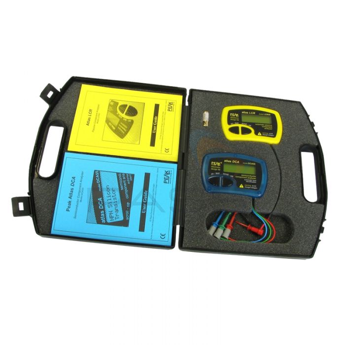
Peak Electronics Component Analyser Pack

- Includes two component analysers
- Bundled in large protective carrying case
- Test a wide variety of component type
This special bundle package includes two of Peak Electronics' component analysers along with a spare battery. Both are supplied in a hard carrying case ideal for protection of the testers and any accessories.
Peak Electronics LCR40 Passive Component Analyser
Connect to and test the status of passive components with ease using this portable instrument. Compatible with all LCR parts (inductors, capacitors and resistors), this instrument instantly identifies the connected component, displays component values and can work out additional information such as the DC resistance of an inductor. Test frequencies are automatically selected to suit the component connected.
- Simple, effective method to check components
- Much less time consuming than using traditional LCR bridges
- Scroll through detailed component information
- Automatic frequency selection
- Supplied with test leads for connection
- Automatic component identification
- Delayed or instant analyser
- Auto power-off
Peak Electronics DCA55 Semiconductor Analyser
Almost identical to the LCR40, the DCA55 is instead used to measure a wide variety of different components including bipolar transistors, enhancement mode MOSFETs, depletion mode MOSFETs, junction FETs (only gate pin identified), low power thyristors and triacs.
- Connect to components in any configuration
- Automatic component type identification
- Automatic pinout identification
- Transistor gain measurement
- MOSFET gate threshold measurement
- PN junction characteristics measurements
- Leakage current measurements
- Auto power on and power off
- Ultra-slim and compact design
DCA55 Tech Specs
| Parameters | Minimum | Typical | Maximum | Notes |
| Peak Test Current into S/C | -5.5mA | 5.5mA | 1 | |
| Peak Test Voltage across O/C | -5.1V | 5.1V | 1 | |
| Measurable Transistor Gain Range (HFE) | 4 | 65000 | 2 | |
| Transistor Gain Accuracy (for HFE<1000) | -3%-5HFE | +3%+5HFE | 2,9 | |
| Transistor VCEO | 2.0V | 3.0V | 2 | |
| Transistor VBE Accuracy | -2%-20mV | +2%+20mV | 9 | |
| VBE Threshold for Darlington Identification | 0.9V | 3 | ||
| VBE Threshold for Darling Identification (Shunted) | 0.8V | 4 | ||
| Acceptable Transistor VBE | 1.8V | |||
| Base-Emitter Shunt Resistance Threshold | 60k | |||
| Transistor Collector-Emitter Test Current | 2.45mA | 2.50mA | 2.55mA | |
| Acceptable Transistor Collector Leakage | 1.0mA | 6 | ||
| MOSFET Gate Threshold Range | 0.1V | 5.0V | 5 | |
| MOSFET Gate Threshold Accuracy | -2%-20mV | +2%-20mV | 5 | |
| MOSFET Drain-Source Test Current | 2.45mA | 2.50mA | 2.55mA | |
| MOSFET Minimum Acceptable Gate Resistance | 8k | |||
| Thyristor/Triac Gate Test Current | 2.5mA | 7 | ||
| Thyristor/Triac Load Test Current | 5mA | |||
| Diode Test Current | 5mA | |||
| Diode Forward Voltage Accuracy | -2%-2mV | +2%+2mV | ||
| VF Threshold for LED | 1.50V | |||
| Short Circuit Detection Threshold | 10Ω | |||
| Battery Type | GP23A 12V Alkaline | |||
| Battery Voltage Range | 7.50V | 12V | ||
| Battery Voltage Warning Threshold | 8.25V | |||
| Inactivity Power-Down Period | 30 secs | |||
| Dimensions (Exc. Test Leads) | 103 x 70 x 20mm | |||
| Operating Temperature Range | 0°C | 50°C | 8 | |
- Between any pair of test clips.
- Collector current of 2.50mA.
- Resistance across reverse biased base-emitter > 60k.
- Resistance across reverse biased base-emitter < 60k.
- Drain-source current of 2.50mA.
- Collector-Emitter voltage of 5V.
- Thyristor quadrant 1, Triac quadrants I and III.
- Subject to acceptable LCD visibility.
- BJT with no shunt resistors.
LCR40 Tech Specs
| Parameters | Minimum | Typical | Maximum | Notes | |
| Resistance | Range | 1R | 2MR | ||
| Resolution | 0.3R | 0.6R | |||
| Accuracy | Typically ±1.0% ±1.2R | 1,2,6 | |||
| Capacitance | Range | 0.5pF | 10000μF | ||
| Resolution | 0.2pF | 0.5pF | |||
| Accuracy | Typically ±1.5% ±1.0pF | 1,2,5 | |||
| Inductance | Range | 1μH | 10H | ||
| Resolution | 0.4μH | 0.8μH | |||
| Accuracy | Typically ±1.5 ±1.6μH | 1,2,4 | |||
| Peak Test Voltage (Across O/C) | -1.05V | +1.05V | |||
| Peak Test Current (Through S/C) | -3.25mA | +3.25mA | |||
| Test Frequency Accuracy |
1kHz | -1.5% | ±1% | +1.5% | |
| 14.925kHz | -1.5% | ±1% | +1.5% | ||
| 200kHz | -1.5% | ±1% | +1.5% | ||
| Sine Purity | Typically -60dB 3rd Harmonic | ||||
| Operating Temperature Range | 10°C | 40°C | 3 | ||
| Battery Operating Voltage | 8.5V | 13V | |||
1. Within 12 months of factory calibration. Please contact us if you require a full re-calibration and/or certification of traceable calibration.
2. Specified at temperatures between 15°C and 30°C.
3. Subject to acceptable LCD visibility.
4. For inductances between 100µH and 100mH.
5. For capacitances between 200pF and 500nF.
6. For resistances between 10Ω and 1MΩ.


