Megger SVERKER900 3-Phase Relay & Substation Test System - Standard

- Upgraded version of the SVERKER900 Basic Kit
- Powerful, multifunctional relay test system
- Built-in touchscreen
Note: there are three versions of the Megger SVERKER900 Test Set available: Basic, Standard and Expert.
This is the Standard kit, which includes the following (new features compared to the Basic Kit are outlined in bold):
- Main Instrument - with timing tests, manual determination of pick-up and drop-out of relay contact and set, inject and measure functions
- Prefault-Fault Instrument - perform timing tests which require simulation of a prefault state before fault simulation
- CT Magnetisiation Instrument - determine the knee point of voltage of the current transformer
- Ramping Instrument - automatically determine pickup threshold and perform time testing
- Sequencer Instrument - simulate sequences such as auto recloser, motor start or re-striking earth faults
Megger's SVERKER900 is a powerful, multifunctional relay and substation test system designed to give professional technicians all the tools they need to perform secondary and primary testing of relay protection within electrical distribution substations, renewable power generation stations and industrial applications.
With the SVEKER900, you'll have everything you need for three-phase secondary testing of protection devices, plus primary testing. You can use this unit for a wide variety of tasks including commissioning and maintenance of distributed/generator power in substations, testing electromechanical, static and numerical protection relays and much, much more.
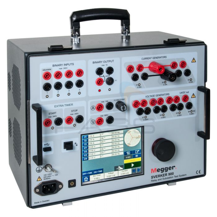
Portable with a built-in carrying handle for easy transportation, the SVERKER900 can be configured to your specific application using a fast response, full colour built-in LCD touchscreen. A wide variety of inputs and outputs cater for practically any testing appliation.
The Megger SVERKER900 Relay Test System is suitable for use with a huge range of relays, including: distance protection/under impedance, overfluxing, synconising/synchornism-check, undervoltage, directional power, undercurrent/underpower, loss of field, negative sequence overcurrent, phase sequence voltage, thermal, overcurrent/ground fault, power factor, overvoltage, DC overcurrent and a wide variety of other relays.
Megger SVERKER900 Interface Breakdown
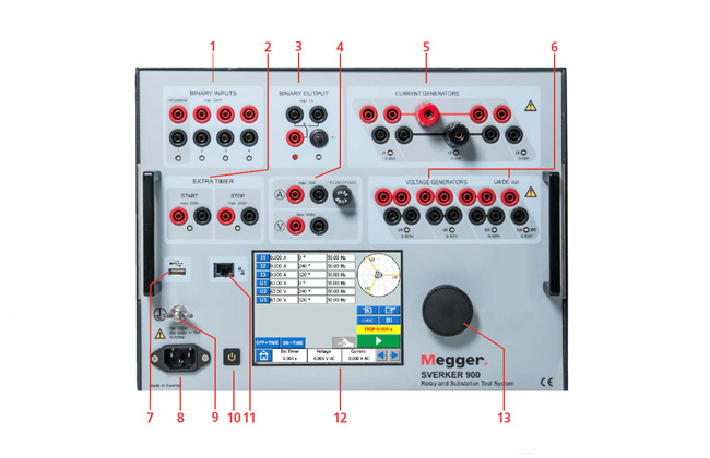
The following table outlines exactly what's included on the SVERKER900's front interface.
 |
|
| 1 - Binary Inputs (1-4) | The binary inputs are independtly programmable gate circuits that permit simple selection of the desired mode for voltage or contact monitoring operations. Binary input 1 has a selectable threshold voltage |
| 2 - Extra Timer | With separate start/stop inputs, the timer can be used to measure both external cycles and sequences initiated by the SVERKER900. The measured time appears on the display. Each input can be set to respond to the presence of abscence of voltage (AC/DC) at a contact |
| 3 - Binary Output | The binary output is used to simulate normally open/normally closed contacts for testing breaker failure schemes, or similar power system operations. In addition it may also be used to switch AC/DC voltages and currents |
| 4 - Current/Voltage | Current and voltage are measured by the built-in ammeter and voltmeter. Resistance, impedance, phase angle, pwer and power factor can also be measured. Readings appear on the display. These instruments can also be used to take measurements in external circuits |
| 5 - Current Generators | The current generators can be used separately, in parallel or series. The current generators deliver maximum compliance voltage to the load constantly during the test, and range changing is done automatically, on-the-fly, under load. |
| 6 - Voltage Generators | The voltage generators can be used separately, in parallel or series |
| 7 - USB | For external keyboard, mouse, saving test data and for updating internal SW |
| 8 - Mains Inlet | |
| 9 - Ground (Earth) Connection | |
| 10 - On/Off Switch | |
| 11 - Ethernet Port | For authorised service actions |
| 12 - Touch Screen | 5.7" full colour LCD |
| 13 - Control Knob | For setting of current, voltage and other parameter values |
Megger SVERKER900 Three-Phase Relay/Substation Test System Key Features
- Full toolbox for substation 3-phase testing
- Three current and four voltage sources
- Standalone functionality
- Rugged and reliable with integrated carrying handle for use in the field
- Generation 900V and 105A in single-phase mode
- Secondary and primary testing
- Fast response LCD colour touchscreen
What's Included?
- SVERKER900 Test Unit
- Ten Jumpers
- Touch Screen Pen
- Test Cable Set
- Protective Cable
- Cable Set (up to 900V)
- Flight Case with Wheels
Call 01642 931 329 or complete the form:
Megger SVERKER900 Technical Specifications
For the full list of tech specs, please see the attached datasheet.
| Specifications are valid for resistive load, at 170-240 voltage supply and ambient temperature +25°C ±3°C (77°F ±5.4°F) after 30 minutes warmup time and in the frequency range of 10Hz to 70Hz. All hardware data are for full scale values. Specifications are subject to change without notice. |
|
| Environment | |
|---|---|
| Application Field | For use in high-voltage substations and industrial environments |
| Operating Temperature | 0 to 50°C (32 to +122°F) |
| Storage/Transport Temperature | -40 to +70°C (-40 to +158°F) |
| Humidiity | 5 to 95% RH, non-condensing |
| Altitude (Operational) | 2000m (6500ft) |
| Shock and Vibration | IEC 60068-2-27 |
| Vibration | IEC 60068-2-6 |
| CE-Marking | |
| EMC | IEC61326-1 |
| LVD | IEC61010-1: 2010 |
| General | |
| Mains Input | 100 to 240V AC, 50/60Hz |
| Current Consumption | 10A (max) |
| Power Consumption | 1800VA (max) |
| Instrument Dimensions | 350 x 270 x 220mm (13.8 x 10.6 x 8.7") |
| Flight Case with Wheels | 615 x 295 x 500mm (24.2 x 11.6 x 19.7") |
| Flight Case | 620 x 295 x 500mm (24.4 x 11.6 x 14.4") |
| Weight | 14.9kg (32.8lbs) - instrument only |
| 29.0kg (64lbs) with accessories and flight case (with wheels, GD-00185) | |
| 23.9kg (52.7lbs) with accessories and flight case (GD-00182) | |
| Display | 5.7" LCD touch screen |
| Available Lanugages | English, French, German, Spanish and Swedish |
| Measurement Section Binary Inputs 1,2, 3, 4 and EXTERNAL TIMER Start/Stop | |
| Number | 6 |
| Type | Dry or wet contacts max, 240V AC or 340V DC |
| Galvanic Isolation | 35 minutes |
| Max Measuring Time | Settable, 0 to 999ms |
| BINARY INPUT 1 | Settable, 0 to 999ms |
| Timer | |
| Range | Inaccuracy |
| 0 to 50ms | ≤1ms |
| 50 to 500ms | ≤2ms |
| >500ms | ≤1% |
| Resolution | 1ms |
| Voltmeter | |
| Measurement Method | AC true RMS DC mean value |
| Insulation | 900V, 1273 peak |
| Input Rating | 900V |
| Inaccuracy (DC Ranges) | |
| 0 to 1V | ±0.5% of reading + 3mV |
| 0 to 10V | ±0.5% of reading + 7mV |
| 0 to 100V | ±0.5% of reading + 30mV |
| 0 to 900V | ±0.5% of reading + 300mV |
| Inaccuracy (AC Ranges) | |
| 0 to 1V | ±1% of reading + 5mV |
| 0 to 10V | ±1% of reading + 10mV |
| 0 to 100V | ±1% of reading + 50mV |
| 0 to 900V | ±1% of reading + 300mV |
| Resolution | 1mV |
| Frequency | |
| Range | 10Hz to 600Hz |
| Inaccuracy | <0.01% |
| Resolution | >10mHz |
| Ammeter | |
| Measurement Method | AC true RMS DC mean value |
| Inaccuracy (DC Ranges) | |
| 0 to 200mA | ±0.5% of reading + 2mA |
| 0 to 1.5A | ±0.5% of reading + 3mA |
| 0 to 10A | ±0.5% of reading + 10mA |
| Inaccuracy (AC Ranges) | |
| 0 to 200mA | ±1% of reading + 2mA |
| 0 to 1.5A | ±1% of reading + 3mA |
| 0 to 10A | ±1% of reading + 20mA |
| Frequency | |
| Range | 10Hz to 600Hz |
| Inaccuracy | <0.01% |
| Resolution | <10mHz |
| Extra Measurements | |
| Power Factor | |
| Range | 0.01 (cap) to 1 to +0.01 (ind) |
| Resolution | <0.01 |
| Inaccuracy | <0.04 |
| Phase Angle (°) | |
| Range | 0 to 360° |
| Resolution | <0.1° |
| Inaccuracy | <0.8° |
| Impedance and Power Measurement | |
| AC | Z(Ω), R(Ω),X (Ω), P(W), S(VA), Q(VAR) |
| DC | R(Ω), P(W) |
| Range | Up to 999kX (X = unit) |
| Binary Outputs | |
| Insulation | 250V AC |
| Current | 1A (max) |
| Voltage | 250V AC |
| Generation Section | |
| Voltage outputs U1, U2, U3 and U4/DC out All voltage sources/generators are galvanically separated from each other and from ground. Floating common return is made by using jumper connectors |
|
| Ranges | |
| 4-Phase AC | 4 x 300V |
| 4-Channel DC | 4 x 300V |
| Power | |
| 4-Phase AC | 4 x 125VA (max) |
| 4-Channel DC | 4 x 125W (max) |
| Inaccuracy | 0.03% range + 0.05% of reading) |
| Distortion (THD + N) | <0.14% typical (0.25% max) |
| Resolution | 10mV |
| Phase | |
| Angle Range | 0 to 360° |
| Inaccuracy | <0.5° (at 50-60Hz) |
| Resolution | 0.1° |
| Frequency | |
| Range | 10Hz to 600Hz |
| Inaccuracy | <0.03% (45 to 66Hz) |
| Resolution | 1mHz |


