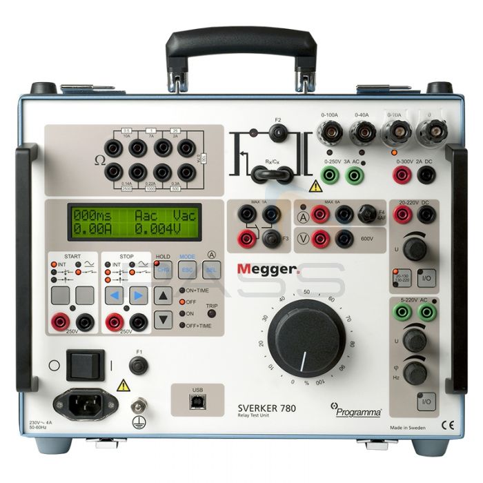
Megger / Programma SVERKER 780 Relay Test Set (230V) - Choice of Case & Leads

- The more powerful version of the SVERKER750
- Portable relay test set made for use with a wide variety of single phase protection
- Powerful measurement functionality
This is the Megger SVERKER780, the upgraded version of the Megger SVERKER750 relay test set.
Both kits are basically identical - they are powerful, multifunctional relay testers which can easily be ported from testing point to testing point. The main difference between the 780 and the 750 is the 780 also includes continuous phase shift and adjustable frequency functions as well as a variable voltage source.
With Megger SVERKER units, you'll have everything you need to test practically any single-phase relay protection. This relay test set is suitable for use with overcurrent, inverse time, undercurrent, ground fault, directional overcurrent, directional ground fault, overvoltage, undervoltage, directional power and a wide variety of other single-phase protection. It's also suitable for use on three-phase protection - just use the SVERKER780 on one phase at a time or alternatively this relay tester is also suitable for use on phase-shifting protective relay systems plus automatic reclosing devices.
The Megger SVERKER780 relay tester is equipped with every measurement function you'll need, all shown in real time on the built-in LCD digital display. This powerful measurement section can display (in addition to time, voltage and current) Z, R, X, S, P, Q, phase angle and cos φ. An integrated voltmeter and ammeter are included for measurements, with the possibility to use the voltmeter as a second ammeter (ideal for testing differential relays).
Need to make a log of your results? No problem with the SVERKER780 - hook the relay tester up to your PC via the built-in serial connection to export your results into Excel documents or use Megger's SVERKER Win software (sold separately) to create fully customisable reports and log data in real-time.
Megger SVERKER780 Feature/Benefit Breakdown
The following table outlines the functionality of the Megger SVERKER780.
 |
|
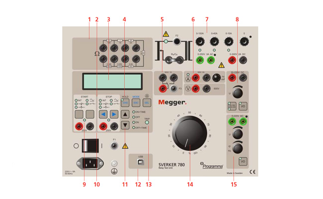
| 1 - Set of Resistors | Made for fine adjustments and regulation of current and voltage |
| 2 - Start and Stop Conditions | The timer's start and stop inputs respond to changes, voltage or contact closing/openings. The timer's start input is also used when testing auto-reclosing relays to synchronise two or more SVERKER units and to start generation with an external signal |
| 3 - Display | Shows time, current, voltage and other parameters. Also used to make settings (access setting mode by pressing MODE button) |
| 4 - Freeze Function (HOLD) | Makes it possible to measure voltage and current as short as a quart of a mains voltage period by saving a reading on the display. Voltage and current readings are frozen when the timer stops. If it doesn't stop, the reading present when the current was interrupted is frozen on the display. |
| 5 - Make/Break Contact | Changes state automatically when a test is started. Can be used (for example) to synchronise two or more SVERKER units, other external equipment or to switch the voltage applied to the protective relay equipment back and forth between faulty and non-faulty. |
| 6 - Ammeter and Voltmeter | Current and voltage are measured by the built-in ammeter/voltmeter. Resistance, impedance, phase angle, power and power factor can also be measured. Reading appear on the display. These instruments can also be used to take measurements in external circuits. The voltmeter can also be used as 2nd ammeter (when testing differential relays, for example, using CSU20A). Current and voltage can be displayed either as amperes or volts or as percantages of a given voltage or current (the present settings of the protective relay equipment, for example). |
| 7 - Current Source | Provides 0-250A AC, 0-250V AC or 0-300V D, depending on the ouput being used. Setting are made using the main knob. The readings of current, voltage and other entities appear on the display. The start switch is used to turn the current source on and off. When time is being measured, this is done in synchronisation with the timer. |
| 8 - Auxiliary Voltage Source | Provides 20-220V DC in two ranges. Equipped with overload protection and separate from the other outputs. Used frequently to supply the object being tested. |
| 9 - Status Indicator | The timer's start and stop inputs are each equipped with indicator lamps which, when lighted, indicate a closed circuit (useful for detecting contact closings/opening) or the presence of voltage. These indicator lamps make it possible (for example) to check circuits before starting a measurement cycle. |
| 10 - Timer Inputs | The timer has separate start and stop inputs, and it can be used to measure both external cycles and sequences initiated by the SVERKER. The measured time appears on the display. Each input can be set to respond to the presence of absence of voltage (AC/DC) at a contact. |
| 11 - Start Switch | Controls the turning on and off of the current source and timer. Can be set to one of four states. ON+TIME. Starts generation and timing simultaneously. Used to test over current, voltage or other parameter relays. Generation continues a) until the protective relay equipment operates and stops the timer or b) until the maximum time expires or the start switch is released if time-limited generation has been selected. OFF function turns of the current source, wherupon generation is interrupted. ON function turns on the current source in the generating state. OFF+TIME function interrupts generation and starts the timer simultaneously. Used when testing current, voltage or other parameter relays. The timer is stopped when the protective relay equipment operates. When automatically reclosing is set to be tested, the SVERKER can be set to start a new generation when the timer's start input is activated by the closing command. |
| 12 - Computer Interface (USB) | Serial port for communication with PC and SVERKER Win PC software |
| 13 - Tripping Indicator | Lights when a stop condition is fulfilled to indicate operation of the protective relay equipment. If the test being conducted incorporates timing, this indicator starts to blink when relay operation occurs. |
| 14 - Main Knob | Used to set current output from the current source |
| 15 - AC Voltage Source | Since the AC voltage source is separated from other outputs, it is set independently of the current source. The AC voltage source is intended primarily for the relay protection equipment's voltage input |
Megger SVERKER780 Relay Test Set Key Features
- Portable solution for testing a wide variety of single phase relays
- Variable frequency and continuous phase shift functions
- Built-in carrying handle for easy transportation
- Rugged and reliable design for field use
- Logical design with simple interface
- Display can show time, voltage, current, Z, R, X, S, P, Q, phase angle and cos φ
- Intergated voltmeter and ammeter
- Variable voltage source
- Serial port for communication with PC and SVERKER Win PC software (software sold separately)
- Two SVERKER units can be synchronised to create a basic 3-phase test set
- Suitable for voltage relays with frequency range from 15Hz up to 550Hz
- Use to plot excitation curves
- Suitable for burden measurements on protective relays
- Impedance, efficiency and polarity measurement possible
What's Included?
| CD-33390 | CD-32300 | CD-32390 | |
| Megger SVERKER780 Relay Test Set | ✔ | ✔ | ✔ |
| GA-00030 Test Lead Set | ✔ | ✖ | ✔ |
| Fix Mounted Case | ✔ | ✖ | ✖ |
| GD-00182 Case | ✖ | ✖ | ✔ |
Optional Accessories
- CD-8102X: SVERKER Win PC Software + RS232/USB Cables (please specify SVERKER serial number when ordering)
- CSU20A: 230V Current and Voltage Source
- PSS750: Phase Selector Switch
- AA-00100: Cable Organiser (Velcro Straps x 10)


