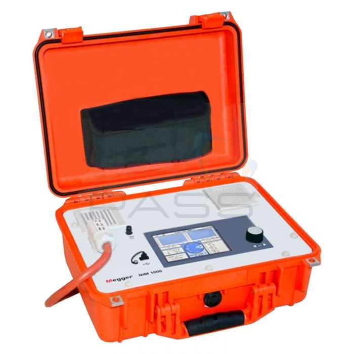
Megger NIM 1000-SET Network Impedance Tester

- Measure the grid impedance of LV grid systems
- Multi-phase measurements with automatic test point switching
- Memory storage and transfer to PC
Megger's NIM 1000 is a self-contained, portable test system designed for measuring the loop impedance in an LV grid, allowing technicians to pinpoint malfunctions before they become a serious issue.
With the Megger NIM 1000, you'll be able to find weak contacts, expose hidden flaws and trigger load-sensitive and neutral faults. Multi-phase measurements are possible, calculating the impedance of the neutral conductor to detect defects which may cause severe safety issues (depending on the grounding conditions of the grid under test). In multi-phase mode, the NIM 1000 will also automatically switch between test points for ease of use.
When testing, the NIM1000 performs many different tasks. It can measure current capacity under real-life conditions, determine voltage dip resulting from given loads and is suitable for testing power supply lines, cables and busbars. All of these parameters combine together to give you a comprehensive snapshot into the operation of the grid and help you to determine areas where power quality and potential issues can be improved upon. It also gives you comprehensive and reliable evaluation of the power grid in terms of current load capacity and voltage fluctuations when under load.
Megger's NIM 1000 measures grid impedance of phase and the neutral conductor up to the 10th harmonic. This ensures that you can determine complex impedance even in situtations where electronic loads and converters are generating strong harmonic currents.
Wherever you're working, the Megger NIM 1000 is ready for the job thanks to compact design, built inside its own hard carrying case. The interface is developed entirely for the needs of LV utilities and for technicians working on complex tasks on LV grids.
Megger NIM 1000 Network Impedance Tester Key Features
- Powerful impedance testing system for use on LV grids
- Up to 1kA test current (80 to 1000A)
- Measures the grid impedance of the phase and neutral conductor up to the 10th harmonic
- Tests impedance (value and phase), resistance, reactance, PEN impedance value, RMS voltage, max test current, short circuit current, continuous short circuit power, net frequency, voltage drop at nominal connected power and max connected power at nominal voltage drop
- Triggers load-sensitive and neutral faults
- Performs multi-phase measurements and switches automatically between test points
- Highly accurate results
- Simple to operate
- Portable design, built inside its own carrying case
- Single and three phase compatible
- Tests in accordance with DIN EN 61557-3 and VDE 041303
What's Included?
- Megger NIM 1000 Network Impedance Tester
- 4 x Kelvin Clamps with 3m Test Leads
- Adapter for Tests on Schuko Outlets
- Megger 1006123 NIM 1000-Z Equipment Set
- Megger 2005383 NIM 1000-A-UK Adapter
- USB Stick (2GB)
- Set of Spare Fuses and Clamps
Megger NIM 1000 Technical Specifications
| Test Current Range | 80 to 1000A (adjustable) |
| Maximum Current (peak) imax (depends on the grid impedance) | ≤ 1000 A @ 400 V ≤ 600 A @ 230 V ≤ 300 A @ 115 V |
| Test Parameters | Z = Impedance (value and phase) R = Resistance (real part) X = Reactance (imaginary part) ZPEN = Impedance value PEN (calculated) Z, R, X und ZPEN are displayed for the power frequency up to the 10th harmonic (phase-N, phase-phase) Urms = RMS voltage Imax = max. test current Is = Short circuit current Skv = Continuous short circuit power f = Net frequency VD = Voltage drop at nominal connected power (in %) Pmax = max. connected power at nominal voltage drop |
| Input Voltage (Serves as Supply Voltage) | 90 V ... 480 V, 50/60 Hz (at test clamps) 90 V … 230 V, 50/60 Hz (at power outlet) |
| Operational Accuracy B (acc to EN 61557-3) | 3% ± 1 digit (at sufficient test current) |
| Test Range (at the above accuracy) | 10 mΩ .. 5 Ω (230 V / 400 V) 10 mΩ .. 2,5 Ω (115 V) |
| Resolution | 1mΩ |
| Test Category | 300V CAT IV |
| Safety Functions | Temperature monitoring, fused clamps |
| Display | Sunlight-readable 5.7" TFT, 640 x 480 pixels |
| Memory | Minimum 1000 test records |
| Interface | USB 2.0 |
| Dimensions | 410 x 175 x 335mm |
| Environmental | Operating Temperature: -20 to 55°C Storage Temperature: -30 to 70°C Humidity: max relative humidity 93% at 30°C |
| Protection | Protection class (IEC 61140, DIN VDE 0140-1): insulated acc to protection class II IP protection (IEC 60529, DIN VDE 0470-1): IP50 (lid open), IP53 (lid closed) |


