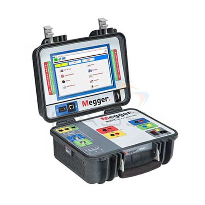
Megger MVCT VT & CT Analyser - Completely Configurable
A lightweight, robust, portable unit, the Megger MVCT VT & CT Analyser can be used to test current and voltage transformers as well as metering and protection class voltage/potential transformers. To this end, it delivers a microprocessor-controlled variable voltage and current output, and provides precision instrumentation to facilitate automatic testing of single and multi-ratio current transformers (CTs) and voltage transformers (VTs). CTs and VTs may be tested within their equipment configurations, for example, mounted in transformers, oil circuit breakers, or switchgear. However, the equipment must be isolated from the electrical system.
Automatic tests may be activated at the push of a button. These tests are performed according to ANSI C57.13; IEC 60044-1; IEC 60044-6; or IEC 61869-2 regulations on relaying /protection class CTs, and IEC 61869-3 on inductive voltage transformers. Alternatively, personalised test plans can be easily created.
The Megger MVCT VT & CT Analyser also offers customisable test reports. It stores complete test files in an easy-to-use, versatile format that facilitates uploading to Megger’s PowerDB Lite Software and enables printing. The Megger MVCT VT & CT Analyser can store over 1000 test results and saturation curves.
Multiple Model Options
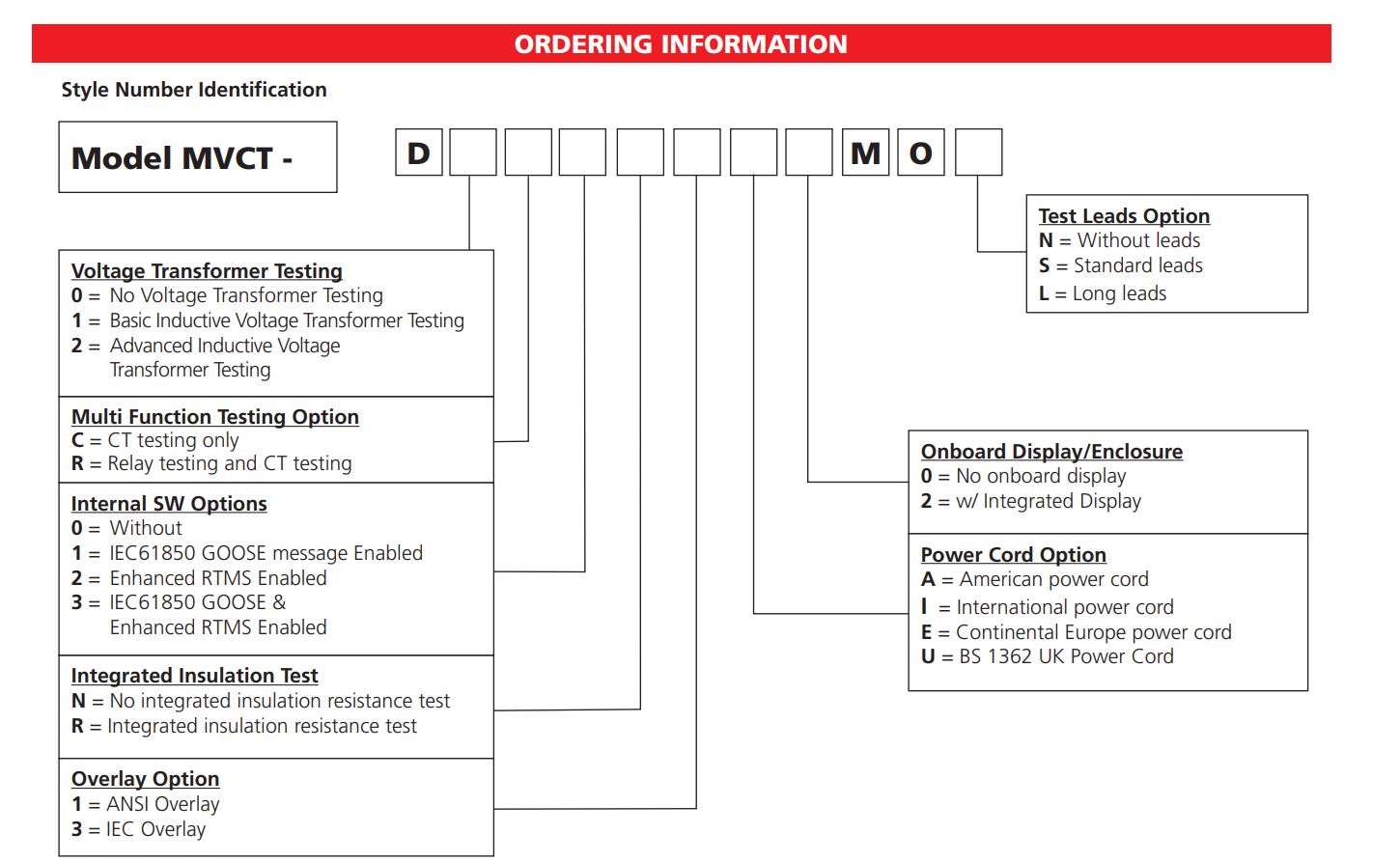
The Megger MVCT VT & CT Analyser is completely configurable allowing you to tailor the model to your requirements.
As illustrated in the ordering information above, the Megger MVCT VT & CT Analyser can be configured to include a display. Megger MVCT VT & CT Analysers with a large, full-colour, high-resolution TFT LCD touchscreen display will show relevant data throughout testing and offer the option to view all readings once the test is complete. Furthermore, the Megger MVCT VT & CT Analyser can be operated via the display, which provides easy access to manual tests and pre-configured/automatic test routines.
Models without a display are controlled via a laptop with Megger’s PowerDB Software or Smart Touch View Interface installed. This enables remote operation.
CT Testing
The Megger MVCT VT & CT Analyser directly connects to multi-ratio CTs. It performs all tests at the push of a button and lead changes, greatly reducing testing time. The Megger MVCT VT & CT Analyser can perform the following tests on CTs:
- Saturation (CT kneepoints up to 30kV and concurrent measurement)
- Ratio, polarity, and burden
- Winding resistance (500/1000V test current)
- Demagnetisation: the Megger MVCT VT & CT Analyser automatically demagnetises CTs after testing and offers a decoupled demagnetisation routine that can be performed as required
- CT burden
- CT grouped testing: demagnetisation, knee points, ratios, saturation curves, winding resistances, polarities, and phase deviation (on all taps of multi-ratio CTs)
VT Testing
In addition to the above, the Megger MVCT VT & CT Analyser can perform the following tests on VTs:
- Ratio, polarity, and ratio with burden
- Winding resistance (500/1000V test current)
- Excitation characteristics and short circuit impedance
The Megger MVCT VT & CT Analyser is a versatile, simple-to-use, portable current and voltage transformer analyser.
Megger MVCT VT & CT Analyser Key Features
- A lightweight, robust, portable current and voltage transformer analyser
- Microprocessor-controlled variable voltage and current transformer analyser
- Precision instrumentation
- Automatic testing of single and multi-ratio CTs and VTs
- CTs and VTs can be tested within their equipment configurations
- Automatic tests are activated at the push of a button
- Tests on relaying/protection class CTs are performed according to ANSI C57.13; IEC 60044-6; or IEC 61869-2
- Tests on inductive VTs are performed according to IEC 61869-3
- Easily create test plans
- Customisable test reports
- Upload test files to Megger’s PowerDB Lite Software
- Print test results (optional printer required)
- Stores over 1000 test results and saturation curves
- Completely configurable unit
- Available with a display and without a display
- Directly connects to multi-ratio CTs
- Tests can be performed on CTs without having to change leads
- CT tests: saturation; ratio, polarity, and burden; winding resistance; demagnetisation; CT burden
- CT grouped testing: demagnetisation, knee points, ratios, saturation curves, winding resistances, polarities, and phase deviation (on all taps of multi-ratio CTs)
- CT kneepoints up to 30kV
- VT tests: ratio, polarity, and ratio with burden; winding resistance; excitation characteristics and circuit impedance
- Versatile, simple-to-use, portable current and voltage transformer analyser
What’s Included?
- Your Choice of Megger MVCT VT & CT Analyser
- Your Choice of Power Cord
- Ethernet Cable
- Instruction Manual
Call 01642 931 329 or complete the form:
Megger MVCT VT & CT Analyser Technical Specifications
| Input | 100 to 265 V, 50 or 60 Hz, 10 A max | |
| Outputs | Output Voltage | 0 to 300 V AC 0 to 300 V DC |
| Output Current | 0 to 1 A eff | |
| Output Power | 300 VA | |
| Inputs | Ranges | 0 to 2/10/50/300 V |
| Resolution | 0.0001 V | |
| Accuracy | ±0.02% of reading | |
| and ± .02% range typical | ||
| ±0.05% of reading and | ||
| ±0.05% range maximum | ||
| Current Measurement | Range 0 to 1.0 A | |
| Resolution 0.0001 A | ||
|
Accuracy ±0.08% of reading ±.08% range typical |
||
| CT Testing | ||
| Ratio | ||
| Standard option range | Accuracy | |
| 0.8 to 2000 | ±0.02% typical ±0.05% maximum | |
| 2000 to 5000 | ±0.03% typical ±0.1%maximum | |
| 5000 to 20000 | ±0.05% typical ±0.2%maximum | |
| Phase Angle | ||
| 3 digits | ||
| Range | 0 to 360 degrees | |
| Resolution | 1 min | |
| Accuracy | ± 3 min typical ±6 maximum | |
| Winding Resistance Test | ||
| Measuring range | 0-30Ω | |
| Accuracy | (at 20° C) 0.5% ±3 mΩ (typical) / 1% ±10 mΩ (guaranteed) (0 – 30 Ω) | |
| Insulation Test | ||
| Test voltage | 1000 VDC, 500 VDC | |
| Measuring range | 20 GΩ | |
| Short circuit current | 1.5 mA nominal | |
| Test current on load | 1 mA at min. pass values of insulation (as specified in BS7671, HD 384 and IEC 364) | |
| Accuracy | 1000 volts ±3% ±2 digits ±0.2% per GΩ | |
| 500 volts ±3% ±2 digits ±0.4% per GΩ | ||
| Communication interfaces | Ethernet | |
| USB | ||
| Environment | ||
| Operating | -10º C to 50º C | |
| Storage | -30º C to 70º C | |
| Standards | IEC 61010 CSA 22.2 CE conformity |
|
| Dimensions | 14” H X 7.5” W X 12” D (36 H cm X 19.3 W cm X 30.5 D cm) |
|
| Weight | 20 lb (9.07 kg) | |
| VT Option Specifications | ||
| Inductive VT Testing | ||
| Outputs | Output Voltage | 0 to 300 V AC |
| Output Current | 0 to 1 A eff | |
| Output Power | 300 VA | |
| Ratio measurement | ||
| Voltage Ratio | Voltage Level | Accuracy |
| 1 to 350 | .6 kV to 35 kV | ±0.03% typical ±0.2% maximum |
| 350 to 1100 | 35 kV to 110 kV | ±0.05% typical ±0.3% maximum |
| 1100 to 2450 | 110 kV to 245 kV | ±0.05% typical ±0.5% maximum |
| Phase Angle Measurement | ||
| Voltage ratio | Voltage Level | Accuracy |
| 1 to 350 | .6 kV to 35 kV | ±3 min typical ±6 min maximum, |
| 350 to 1100 | 35 kV to 110 kV | ±3 min typical ±6 min maximum |
| 1100 to 2450 | 110 kV to 245 kV | ±3 min typical ±6 min maximum. |
| Winding Resistance Measurement | ||
| Resolution | 1m Ω | |
| Guaranteed accuracy | (at 20° C) ±0.5% + 1 mΩ | |
| Insulation Test | ||
| Test voltage | 1000 VDC, 500 VDC | |
| Measuring range: | 20 GΩ | |
| Short circuit current | 1.5 mA nominal | |
| Test current on load | 1 mA at min. pass values of insulation (as specified in BS7671, HD 384 and IEC 364) |
|
| Accuracy | 1000 volts ±3% ±2 digits ±0.2% per GΩ 500 volts ±3% ±2 digits ±0.4% per GΩ |
|
| Relay Option Specifications | ||
| Outputs | All outputs are independent from sudden changes in line voltage and frequency. This provides stable outputs not affected by sudden changes in the power source. All outputs are regulated so changes in load impedance do not affect the output. | |
| Output current | Output power ratings are specified in AC rms values and peak power ratings. Output Current Power 1 ampere 15 VA 15.0 V rms continuous | |
| Output current power | 1 ampere 15 VA 15.0 V rms continuous | |
| Max V / duty cycle | 4 amperes 200 VA (282 peak) | |
| 50.0 V rms continuous | ||
| 15 amperes 200 VA (282 peak) | ||
| 13.4 V rms continuous | ||
| 30 amperes 200 VA (282 peak) | ||
| 6.67 V rms continuous | ||
| 75 amperes 300 VA (424 peak) | ||
| 5.00 V rms 90 cycles | ||
| DC 200 Watts | ||
| AC voltage output | Outputs are rated with the following ranges |
Output volts power max I |
| 30 volts 150 VA 5 amps | ||
| 150 volts 150 VA (see Power V) | ||
| 300 volts 150 VA 0.5 amps | ||
| DC 150 watts | ||
| Duty Cycle: Continuous | ||
| Metering | Measured output quantities such as AC amperes, AC Volts, DC volts or DC amperes, and time may be simultaneously displayed on the large, color TFT LCD, optional STVI touch screen. The AC and DC outputs display the approximate voltage/current output before initiating the outputs. | |
| AC voltage amplitude | Accuracy | ±0.05% reading + 0.02% range typical |
| ±0.15% reading + 0.05% range maximum | ||
| Resolution | .01 | |
| Measurements | AC RMS | |
| Ranges | 30, 150, 300 V | |
| AC current amplitude | Accuracy | ±0.05% reading + 0.02% range typical, |
| ±0.15% reading + 0.05% range maximum | ||
| Resolution | .001/.01 | |
| Measurements | AC RMS | |
| Ranges | 30, 60 A | |
| DC voltage amplitude | Accuracy | 0.1% range typical, 0.25% range maximum |
| Resolution | .01 | |
| Measurements | RMS | |
| Ranges | 30, 150, 300 V | |
| DC current amplitude | Accuracy | ±0.05 % reading + 0.02 % range typical |
| ±0.15 % reading + 0.05 % range maximum |
||
| Resolution | .001/.01 | |
| Measurements | RMS | |
| Ranges | 30 A | |


