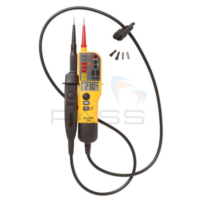
Fluke T130 Two-Pole Voltage/Continuity Tester

- Dual indicators - LED lights and LCD screen
- Range from 6 to 690V
- Ideal for professional electricians
What's New?
Fluke has updated the T130 Two-Pole Voltage and Continuity Tester to include the following:
- Improved safety features, including a CableHealth function (see below)
- Cable able to withstand 5000 bend cycles in both directions to 150°, exceeding the EN 61243-3 standard by up to three times (see the video below)
- Rugged design: the most durable Fluke Two-Pole Voltage Testers to date
NEW CableHealth Function
This function is designed to ensure the safety and reliability of the Fluke T130 Two-Pole Voltage and Continuity Tester. It runs continuously and automatically in the background, requiring zero input from the operator; it checks the soundness and continuity of the Fluke T130 Two-Pole Voltage and Continuity Tester’s test lead.
The CableHealth function will verify the condition of the Fluke T130 Two-Pole Voltage and Continuity Tester’s test lead before, during, and after measurements. A fault is indicated via the illumination of a red band (the CableHealth indicator); this band will illuminate even if an intermittent fault is detected. When this light is dark, the user knows that the test lead is in good health.
The integration of a NEW CableHealth function and indicator into the Fluke T130 Two-Pole Voltage and Continuity Tester ensures that the user is continuously and immediately informed as to the safety and reliability of his/her instrument. It enables electricians to work more safely and reliably.
Fluke T130 Two-Pole Voltage and Continuity Tester Overview
See exactly what the voltage level is with Fluke's T130!
The upgraded version of the T90 and T110, the T130 includes a backlit LCD which shows voltage level as a digital value alongside LED indicators of voltage up to 690V. It also includes a display hold function, allowing the value taken to be temporarily stored on the screen.
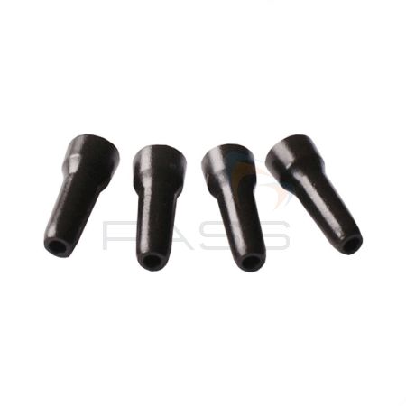
Highly popular with electricians, the T130 is equipped with GS38-compliant caps and can be used to perform continuity testing (with the ability to switch the buzzer on and off) and also indicates polarity.
Additional functions of this tester include single-pole phase detection, a vibration indicator when under load, and a built-in electrical torch.
Fluke T130 Two-Pole Voltage/Continuity Tester Key Features
- Dual voltage indicator - LED step lights and built-in backlit LCD screen
- Range from 6 to 690V
- Continuity test with buzzer (can be switched on/off)
- Single pole test for phase indication
- Responds in under a second
- Can be used even when the batteries are discharged
- GS38-compliant probe tips
- Low battery indication
- Probe docking system for easy storage
- WearGuard indicator shows damage to test leads
- Data hold function freezes the last value taken on the screen
Fluke T-Series Comparison Chart
The following table outlines the difference between each of Fluke's T-series Two-Pole Voltage and Continuity Testers:
| T90 | T110 | T130 | T150 | |
| Voltage AC/DC | 12V - 690V | 12V - 690V | 6V - 690V | 6V - 690V |
| Continuity | 0-400kΩ | |||
| Frequency | 0/40-400Hz | |||
| Phase Rotation | - | 100V-690V | ||
| Resistance Measurement | - | - | - | Up to 1999Ω |
| Response Time (LED Indicator) | <0.5s | |||
| 200kΩ Input Impedance | Current Draw 3.5mA @ 690V Current Draw 1.15mA @ 230V |
|||
| 7kΩ Input Impedance (with load buttons pressed) | - | Current draw 30mA @ 230V | ||
| Safety Rating | CAT II 690V CAT III 600V |
CAT III 690V CAT IV 600V |
||
| IP Rating | IP54 | IP54 | IP64 | IP64 |
| Backlit LED indicator | ✓ | ✓ | ✓ | ✓ |
| Backlit LCD digital display | - | - | LCD | LCD |
| Continuity test—visual results | ✓ | ✓ | ✓ | ✓ |
| Continuity test—audible results | ✓ | ✓ with on/off | ✓ with on/off | ✓ with on/off |
| Vibratory indicator under load | - | ✓ | ✓ | ✓ |
| Display hold | - | - | ✓ | ✓ |
| Voltage test | ✓ | ✓ | ✓ | ✓ |
| Indication of polarity | ✓ | ✓ | ✓ | ✓ |
| Resistance measurement | - | - | - | ✓ |
| Switchable load | - | ✓ | ✓ | ✓ |
| Single pole test for phase detection | ✓ | ✓ | ✓ | ✓ |
| Rotary field indicator | - | ✓ | ✓ | ✓ |
| Probe tip protection | ✓ | ✓ | ✓ | ✓ |
| Voltage display with discharged batteries | ✓ | ✓ | ✓ | ✓ |
| Electrical torch function | - | ✓ | ✓ | ✓ |
| Wear indicator test lead wire | ✓ | ✓ | ✓ | ✓ |
Offers
 Spend £150+ (Ex VAT) on any qualified Fluke or Beha-Amprobe product(s) and claim a free tool of your choice from the list at Fluke Promotion. Valid February 17 2025 - July 31 2025.
Claims are made direct to Fluke. Terms and conditions apply.
- Free Pack of 4 Fluke GS38 Probe Caps - 4083642-PACK, typically £10.00
Fluke T-Series Technical Specifications
| T90 | T110 | T130 | T150 | |
| Voltage AC/DC | 12V to 690V | 12V to 690V | 6V to 690V | 6V to 690V |
| Continuity | 0 to 400kΩ | |||
| Frequency | 0/40 to 400Hz | |||
| Phase Rotation | - | 100V to 690V | ||
| Resistance Measurement | - | - | - | Up to 1999Ω |
| Response Time (LED indicator) | <0.5s | |||
| 200kΩ Input Impedance |
Current draw 3.5mA @ 690V, Current draw 1.15mA @ 230V | |||
| 7kΩ Input Impedance (with load buttons pressed) |
- | Current draw 30mA @ 230V | ||
| Safety Rating | CAT II 690V CAT III 600V |
CAT III 690V, CAT IV 600V | ||
| IP Rating | IP54 | IP64 | IP64 | IP64 |


