Fluke SMFT-1000 Solar Multifunction PV Tester – Pro Kit

- An all-in-one photovoltaic testing solution
- Test solar systems (up to 1000 V)
- Includes Fluke Advanced TruTest Software
- Optional 1-Year Premium Care (UK Only)
Fluke SMFT-1000 Solar Multifunction PV Tester – Pro Kit
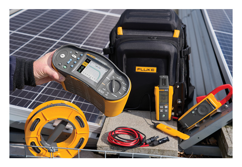
The Fluke SMFT-1000 Solar Multifunction PV Tester is an all-in-one photovoltaic testing solution, performance analyser, and I-V curve tracer that can be used to check the safety and functionality of solar/PV installations operating at a maximum of 1000V. Specifically designed for solar professionals, such as electricians and technicians involved in commissioning, maintaining, and troubleshooting PV systems, the Fluke SMFT-1000 is compliant with IEC’s 62446-1 standard.
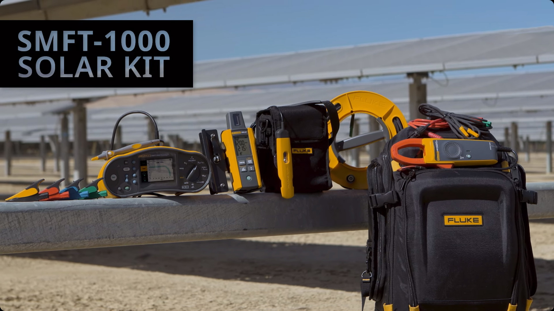
Watch our videos all about the SMFT-1000 and find out about its unique features, especially for Solar professionals.
Optional Fluke Premium Care - 1 Year (UK Only)
- Accidental damage and repair costs included
- Expedited calibration and repair
- Annual tool inspection, calibration, and updating
- Replacement of damaged accessories (Some limitations apply, see Fluke Terms and Conditions)
Select the Premium Care option in the dropdown box when choosing the model you wish to purchase, only available for users in the UK. Please visit our Blog for more information.
TruTest Software
 Unlike the Standard Kit, the Pro Kit is supplied with Fluke’s Advanced TruTest Software, an asset management, data storage, analysis, and reporting platform. Using this program, you can save time processing results and compiling reports. Fluke’s Advanced TruTest Software allows you to:
- Import measurements from the Solar Multifunction PV Tester directly to your PC
- Manage/organise data
- Create reports compliant with directives such as IEC 62446-1
- Analyse I-V curves using pass/fail visuals
- Monitor I-V curve changes over time
- Compare data
Visual Inspection
Includes a setting for recording visual observations, ensuring compliance with IEC regulations. This information can be imported into Fluke’s Advanced TruTest Software and may be incorporated into reports.
Tests
Dedicated controls on the Tester’s front panel provide access to the following tests:
- Resistance
- Polarity
- Voltage and Current
- Power AC/DC and Function
- Insulation Resistance
- I-V Curve
- Diode
The Fluke SMFT-1000 Solar Multifunction PV Tester also includes several auto-test sequences such as the one below.
| Full Sequence Safety Testing - IEC 62446-1 Category 1 | Protective resistance earth RLO |
| Voltage on open circuit, including polarity VOC | |
| Short circuit current ISC | |
| Insulation resistance RINS | |
| System Performance Testing - IEC 62446-1 Category 2 | I-V Curve tracing and software analysis with TruTest™ |
| Irradiance, temperature, tilt, cardinal direction |
Auto Test mode allows you to perform automatic test sequences in a variety of combinations, for example:
- With or without the insulation test
- Category 1 or category 1 and 2 tests (compliant with IEC 62446-1)
- Protection Class I or Protection Class II tests (compliant with IEC 62446-1)
I-V Curve Tracing
The Fluke SMFT-1000 Solar Multifunction PV Tester is supplied with a Fluke IRR2-BT Irradiance Meter that gathers real-time temperature and irradiance data, wirelessly transferring it to the Fluke SMFT-1000. The Fluke IRR2-BT Irradiance Meter provides accurate, up-to-the-moment I-V curve readings and the tester displays the curve as the data loads, allowing you to compare it against the manufacturer’s module specifications. This means you can quickly and easily confirm measurements without a laptop/tablet. Should the wireless connection between the irradiance meter and MFT falter, the Fluke IRR2-BT will log data to its memory for up to seventeen hours.
Keep the Leads
Fluke’s Keep the Leads system means you only need to connect test leads to the solar installation once. This saves time and reduces user errors, allowing you to work more simply and quickly.
Colour Screen
Also adding to the Fluke SMFT-1000's ease of use is its colour display with on-screen instructions that guide you through each test procedure.
The Fluke SMFT-1000 Solar Multifunction PV Tester is a complete solar installation testing solution optimised for speed and simplicity.
Product Testimonial
Videos
PASS Presents - The Ultimate Tool for Solar Pros
Fluke SMFT 1000 Solar Kit Introduction
Fluke TruTest Software
I-V Curve and Saftey Testing
Fluke IRR2-BT Wireless Solar Irradiance Meter
Key Features
- An all-in-one photovoltaic testing solution, performance analyser, and I-V curve tracer
- Test the safety and functionality of solar/PV installations operating at a maximum of 1000V
- Specifically designed for electricians and technicians involved in commissioning, maintaining, and troubleshooting solar/PV installations
- Complaint with IEC 62446-1
- Supplied with Fluke Advanced TruTest Software: an asset management, data storage, analysis, and reporting platform
- Features a setting for recording the details of visual inspections
- Resistance, polarity, voltage, current, power AC/DC, function, insulation resistance, I-V curve, and diode tests
- Auto Test mode
- IRR2 Irradiance Meter gathers real-time temperature and irradiance data
- IRR2 Meter connects wirelessly to the SMFT-1000 enabling real-time data transfer
- IRR2 Meter will log readings for up to 17 hours if the wireless connection breaks
- Displays I-V curve as it loads making it quicker and easier to confirm measurements without a laptop/tablet
- Keep the Leads system for one-time lead configuration
- Colour display with on-screen instructions
- A complete solar installation testing solution optimised for speed and simplicity.
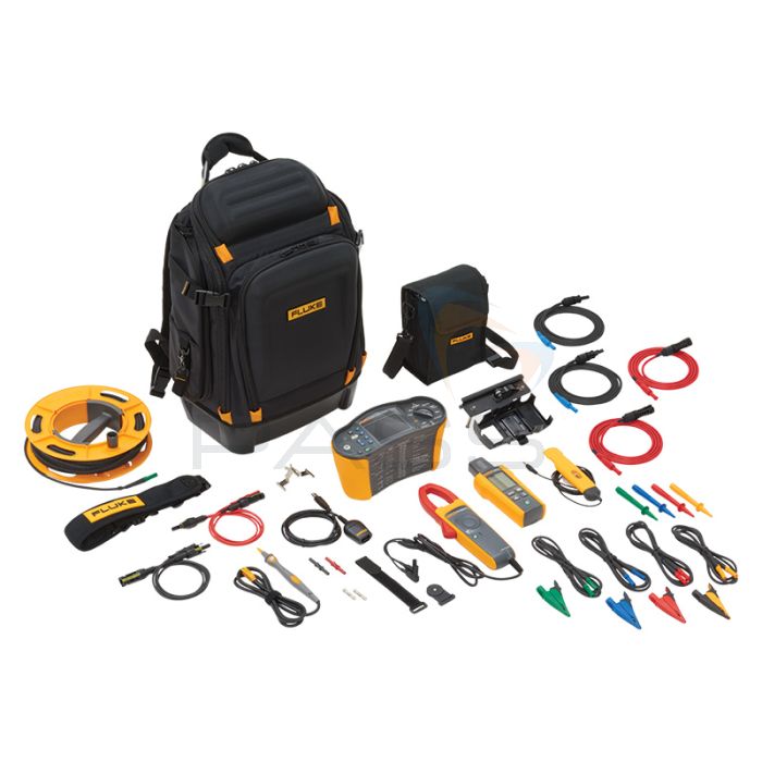
What Accessories Come with the Fluke SMFT1000?
-
Fluke SMFT-1000 Solar Multifunction PV Tester
- Carry Strap
- Fuse Pack
- Adapter Cable IRDA Optical-to-USB
- Zero Adapter
- Fluke SMFT Professional Tool Backpack
-
Fluke IRR2-BT Wireless Solar Irradiance Meter
- Fluke 80PR-IRR External Temperature Probe
- Mounting Bracket for Solar Panel
- Carry Case
-
Fluke i100 AC/DC Current Clamp (100 A)
- TPAK Magnet Set
- Fluke Advanced TruTest Software
- Fluke MC4 Solar Clamp Test Lead Set
- Fluke TP1000 Test Probe with Remote Test Button
- Fluke TL1000 Test Lead Set
- Fluke TL1000-MC4 Test Lead Set
- Fluke TL1000/30M Test Lead on Reel
- Coupler Set
- 6x AA Batteries
- Optional 1-Year Premium Care (UK Only)
Product Range
- Fluke SMFT-1000/PRO Solar Multifunction PV Tester - Pro Kit
- Fluke SMFT-1000 PRO/FPC EU Solar Multifunction PV Tester - Pro Kit & 1-Year Premium Care (UK Only)


Offers
 Spend £150+ (Ex VAT) on any qualified Fluke or Beha-Amprobe product(s) and claim a free tool of your choice from the list at Fluke Promotion. Valid February 17 2025 - July 31 2025.
Claims are made direct to Fluke. Terms and conditions apply.
Fluke SMFT-1000 Solar Multifunction PV Tester Technical Specifications
| Protective conductor resistance (RLo) | |||
|---|---|---|---|
| Display range | Measuring range | Resolution | Accuracy |
| 0.00 Ω - 19.99 Ω | 0.20 Ω - 19.99 Ω | 0.01 Ω | ± (2 % + 2 Digit) |
| 20.0 Ω- 199.9 Ω | 20.0 Ω - 199.9 Ω | 0.1 Ω | ± (2 % + 2 Digit) |
| 200 Ω - 2000 Ω | 200 Ω - 2000 Ω | 1 Ω | ± (5 % + 2 Digit) |
| Test Current | ≥ 200 mA (≤ 2Ω + Rcomp) | ||
| Test voltage | 4 V DC … 10 V DC | ||
| Polarity reversing | Yes | ||
| Test lead zero (Rcomp) | Up to 3 Ω | ||
| PV module/PV string, open-circuit voltage (Voc) | |||
| Display range | Measuring range | Resolution | Accuracy |
| 0.0 V - 99.9 V | 5.0 V - 99.9 V | 0.1 V | ± (0.5 % + 2 Digit) |
| 100 V - 1000 V | 100 V - 1000 V | 1 V | ± (0.5 % + 2 Digit) |
| Polarity test | Yes | ||
| PV module/PV string, short-circuit current (Is/c) | |||
| Display range | Measuring range | Resolution | Accuracy |
| 0.0 A - 20.0 A | 0.2 A - 20.0 A | 0.1 A | ± (1 % + 2 Digit) |
| Insulation resistance (RINS) | |||
| Display range | Measuring range | Resolution | Accuracy |
| 0.00 MΩ - 99.99 MΩ | 0.20 MΩ - 99.99 MΩ | 0.01 MΩ | ± (5 % + 5 Digit) |
| 100.0 MΩ - 199.9 MΩ | 100.0 MΩ - 199.9 MΩ | 0.1 MΩ | ± (10 % + 5 Digit) |
| 200 MΩ - 999 MΩ | 200 MΩ - 999 MΩ | 1 MΩ | ± (20 % + 5 Digit) |
| Blocking diode checking (Vbd) | |||
| Display range | Measuring range | Resolution | Accuracy |
| 0.00 V DC - 6.00 V DC | 0.50 V DC - 6.00 V DC | 0.01 V DC | ± (5 % + 10 Digit) |
| Surge protection device (SPD) | |||
| Display range | Measuring range | Resolution | Accuracy |
| 0 V DC - 1000 V DC | 50 V DC - 1000 V DC | 1 V DC | ± (10 % + 5 Digit) |
| AC/DC voltage measurement via 4 mm test sockets | |||
| Display range | Measuring range | Resolution | Accuracy |
| 0.0 V AC - 99.9 V AC | 5.0 V AC - 99.9 V AC | 0.1 V | ± (2.5 % + 2 Digit) |
| 100 V AC - 700 V AC | 100 V AC - 700 V AC | 1 V | ± (2.5 % + 2 Digit) |
| 0.0 V DC - 99.9 V DC | 5.0 V DC - 99.9 V DC | 0.1 V | ± (2.5 % + 2 Digit) |
| 100 V DC - 1000 V DC | 100 V DC - 1000 V DC | 1 V | ± (2.5 % + 2 Digit) |
| Detection AC/DC | Yes (Automatic) | ||
| + / - polarity check | Yes | ||
| AC/DC with i100 clamp | |||
| Display range | Measuring range | Resolution | Accuracy (DC, AC 50 Hz/60 Hz) |
| 0.0 A DC – 100 A DC | 1.0 A DC – 100 A DC | 0.1 A | ± (5 % + 2 Digit) * |
| 0.0 A AC – 100 A AC TRMS | 1.0 A AC – 100 A AC TRMS | 0.1 A | ± (5 % + 2 Digit) * |
| * i100 clamp tolerances not inclusive | |||
| i100 Clamp Tolerances | |||
| Display range | Measuring range | Output signal | Accuracy (DC, AC 50 Hz/60 Hz) |
| N/A | 1 A - 100 A DC or AC < 1 kHz | 10 mV/A AC/DC | ± (1.5 % + 0.1 A) |
| AC/DC Power measurement (with i100 clamp) | |||
| Display range | Measuring range | Resolution | Accuracy (DC, AC 50 Hz/60 Hz) |
| 0.0 V AC - 700 V AC 0.0 V DC - 1000 V DC |
5.0 V AC - 700 V AC 5.0 V DC - 1000 V DC |
0.1 V | ± (2.5 % + 2 Digit) |
| 0 A AC/DC - 100 A AC/DC | 1 A AC/DC- 100 A AC/DC | 0.1 A | ± (6.5 % + 3 Digit) |
| 0 kW/kVA – 100 kW/kVA | 5 kW/kVA – 100 kW/kVA | 1 kW/kVA | ± (10 % + 4 Digit) |
| General Specifications | |||
| SMFT-1000 size | 10 cm x 25.0 cm x 12.5 cm (3.8 in x 9.8 in x 4.9 in) | ||
| SMFT-1000 weight | 1.4 kg (3.09 lb) | ||
| Battery | 6 AA IEC LR6 | ||
| Operating temperature | 0 °C to 50 °C (32 °F to 122 °F) | ||
| Storage temperature | -30 °C to 60 °C (-22 °F to 140 °F) batteries removed | ||
| Operating altitude | up to 2000 m | ||
| Storage altitude | up to 2000 m | ||
| Safety | |||
| SMFT-1000 PV Analyzer | IEC 61010-1 Pollution Degree 2 IEC 61010-2-034 CAT III 1000 V dc, CAT III 700 V AC |
||
| i100 Current Clamp | IEC 61010-2-032, Type D (for insulated conductors), 1000 V | ||
| Accessories | IEC 61010-031 | ||
| TL1000-MC4 | CAT III 1500 V, 20 A | ||
| TP1000 Remote Probe (with cap) | CAT IV 600 V, CAT III 1000 V, 10 A | ||
| TP1000 Remote Probe (without cap) | CAT II 1000 V, 10 A | ||
| TL1000 Test Leads | CAT III 1000 V, 10 A | ||
| TL1000/30M Test Leads | CAT III 1000 V, CAT IV 600 V, 5 A (on reel) 10 A (fully extended) |
||
| TP74 Test Probes (with cap) | CAT III 1000 V, 10 A | ||
| TP74 Test Probes (without cap) | CAT II 1000 V, 10 A | ||
| AC285 Alligator Clip | CAT III 1000 V, 10 A | ||
| Performance | IEC 61557-1, IEC 61557-2, IEC 61557-4, IEC 61557-10 | ||
| Electromagnetic Compatibility (EMC) | |||
| International | IEC 61326-1: Portable Electromagnetic Environment, CISPR 11: Group 1, Class A Group 1: Equipment has intentionally generated and/or uses conductively coupled radio frequency energy that is necessary for the internal function of the equipment itself. Class A: Equipment is suitable for use in all establishments other than domestic and those directly connected to a low-voltage power supply network that supplies buildings used for domestic purposes. There may be potential difficulties in ensuring electromagnetic compatibility in other environments due to conducted and radiated disturbances. Caution: This equipment is not intended for use in residential environments and may not provide adequate protection to radio reception in such environments. |
||
| Wireless Radio Module | |||
| Frequency Range | 2.402 GHz to 2.480 GHz | ||
| Output Power | 8 dBm | ||


